Mechanical biaxial tension tester with variable proportion loading

A two-way stretching, mechanical technology, applied in the direction of applying stable tension/pressure to test the strength of the material, to achieve the effect of reducing friction

Inactive Publication Date: 2010-12-08
HARBIN INST OF TECH
View PDF5 Cites 53 Cited by
  • Summary
  • Abstract
  • Description
  • Claims
  • Application Information

AI Technical Summary

Problems solved by technology

[0004] The purpose of the present invention is to solve the problem that the existing biaxial tensile test device cannot realize the variable ratio loading under the complex loading path, and then provide a mechanical biaxial tensile tester with variable ratio loading

Method used


Image

  • Mechanical biaxial tension tester with variable proportion loading
  • Mechanical biaxial tension tester with variable proportion loading
  • Mechanical biaxial tension tester with variable proportion loading

Examples


specific Embodiment approach 1

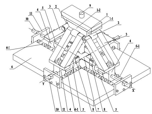
[0008] Specific implementation mode one: combine Figure 1 to Figure 6 Describe this embodiment, the mechanical biaxial tensile tester of variable ratio loading of this embodiment comprises workbench 6, four diagonal struts 3, four tension-compression sensors 5 and four collets 8; The tester also includes an inclined slider 1, four rolling bearings 2 and four horizontal sliders 4. The inclined slider 1 is an inverted trapezoidal quadrangular platform, and the workbench 6 is provided with a cross slide 6-1. The cross-shaped test piece 7 is placed above the cross chute 6-1, and the four ends of the cross-shaped test piece 7 are respectively fixedly connected with a clamp 8, and each clamp 8 is fixedly connected with a tension-compression clamp on the outer end surface of the clamp 8. Sensor 5, the outer end of each tension and pressure sensor 5 is fixedly connected with a horizontal slider 4, each horizontal slider 4 is installed on the workbench 6, and each horizontal slider 4 ...

specific Embodiment approach 2

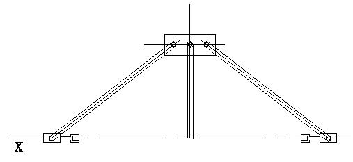
[0010] Specific implementation mode two: combination figure 2 and image 3 To describe this embodiment, the included angle α between each diagonal brace 3 and the horizontal plane in this embodiment is 45°. With such arrangement, the diagonal brace can well decompose the force to the horizontal direction, and at the same time satisfy the limitation on the moment. Other compositions and connections are the same as in the first embodiment.

specific Embodiment approach 3

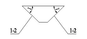
[0011] Specific implementation mode three: combination figure 1 , Figure 4 and Figure 5 Describe this embodiment, the angle β between the trapezoidal inclined surface 1-1 on the left and right sides of the inclined slider 1 of the present embodiment and the upper end surface is 45°, the trapezoidal inclined surface 1-2 on the front and rear sides of the inclined slider 1 and the upper end surface The included angle γ of the end faces is 78°. With such settings, a ratio loading of 8:1 in the X-Y direction is obtained. Other compositions and connections are the same as those in Embodiment 1 or Embodiment 2.


PUM


Abstract

The invention discloses a mechanical biaxial tension tester with variable proportion loading, relating to a biaxial tension tester. The invention solves the problem that the traditional biaxial tension testing device can not realize variable proportion loading under a complex loading path. In the invention, a slanting slide block is an inverted trapezoidal quadrangular frustum pyramid, a workbench is provided with a cruciform chute, a cruciform test piece is arranged above the cruciform chute, four ends of the cruciform test piece are respectively and fixedly connected with a clamping head, a tension-compression sensor is fixedly connected to the outer end surface of each clamping head, the outer end of each tension-compression sensor is fixedly connected with a horizontal slide block, each horizontal slide block is installed on the workbench, the lower end of each slant beam is fixedly connected with a horizontal slide block, a rolling bearing is installed at the upper end of each slant beam, and each rolling bearing is contacted with a corresponding trapezoidal inclined plane of each slant beam and rolls on the corresponding trapezoidal inclined plane of each slant beam. The invention is suitable for a tension test of the cruciform test piece.

Description

technical field [0001] The invention relates to a two-way tensile tester, in particular to a mechanical two-way tensile tester with variable ratio loading. Background technique [0002] Since the establishment of plate and shell theory, plate and shell structures have been used in more and more fields, especially in the field of aerospace, most of the space containers are two-way force-bearing structures, such as spherical containers and thin-walled cylindrical parts. In order to solve its structural and performance problems, since the 1940s, more and more people have devoted themselves to bidirectional tensile tests. So far, the biaxial tensile test has not been well resolved, a large part of the reason is the complexity of the design of the double tensile device. Scholars have studied different types of biaxial tensile test methods in different periods, such as double tensile test under uniaxial tension, film swelling double tensile test, pressure vessel double tensile te...

Claims


Application Information

Patent Timeline
Patent Type & Authority Applications(China)
IPC IPC(8): G01N3/08
Inventor 徐文臣陈勇孙圣迪单德彬
Owner HARBIN INST OF TECH
Why Eureka
Try Eureka