High-resolution rotation-speed measuring device

A speed measurement, high-resolution technology, applied in the direction of measuring device, linear/angular velocity measurement, velocity/acceleration/shock measurement, etc., can solve the problems of missing sampling pulse, increase of measurement resolution, system error, etc., and achieve measurement resolution The effect of improving the rate, improving the measurement resolution and improving the reliability

Inactive Publication Date: 2012-05-02
ZHEJIANG UNIV
View PDF0 Cites 0 Cited by
  • Summary
  • Abstract
  • Description
  • Claims
  • Application Information

AI Technical Summary

Problems solved by technology

However, the number of metal protrusions or the number of light-transmitting holes on a single turntable cannot be increased infinitely due to volume limitations, and the processing speed of existing sensing devices and signal conditioning circuits is also limited.
The above-mentioned rotational speed measurement device has the following disadvantages: 1) The measurement resolution depends on the number of metal protrusions or light-transmitting holes on the turntable, and this number is limited by the mechanical size, so it cannot be designed much
Therefore, the increase in measurement resolution is limited
2) With the increase of the rotational speed, limited by the processing speed of the sensing device and signal conditioning circuit, the sampling pulse will be lost, forming a system error and affecting the measurement accuracy

Method used


Image

  • High-resolution rotation-speed measuring device
  • High-resolution rotation-speed measuring device
  • High-resolution rotation-speed measuring device

Examples


Embodiment Construction

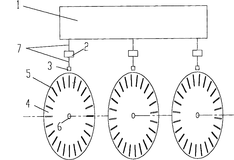
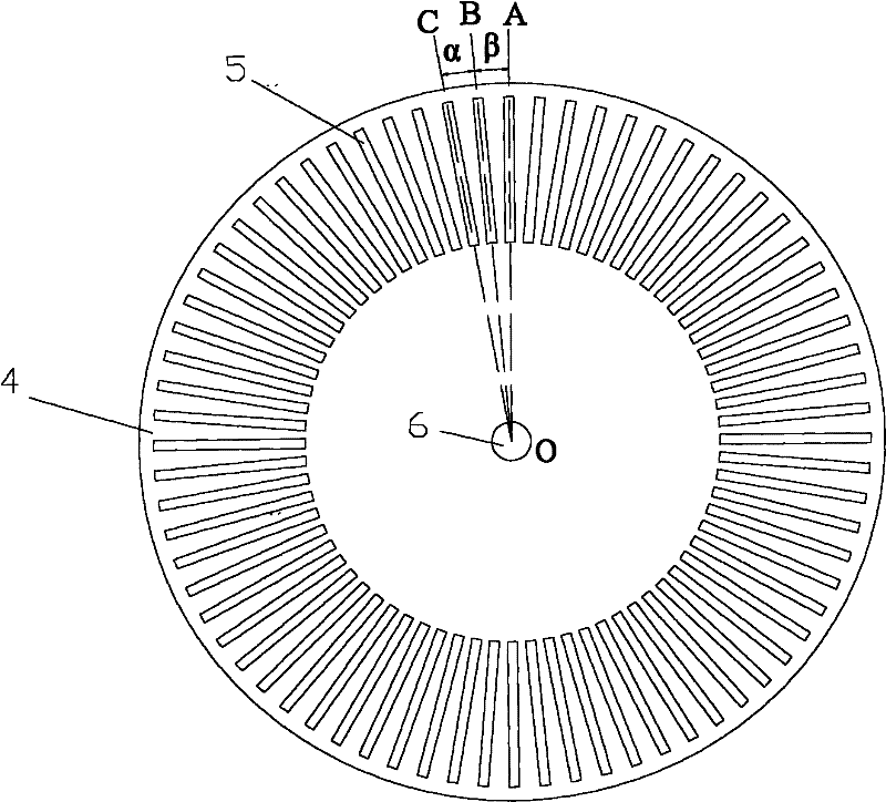
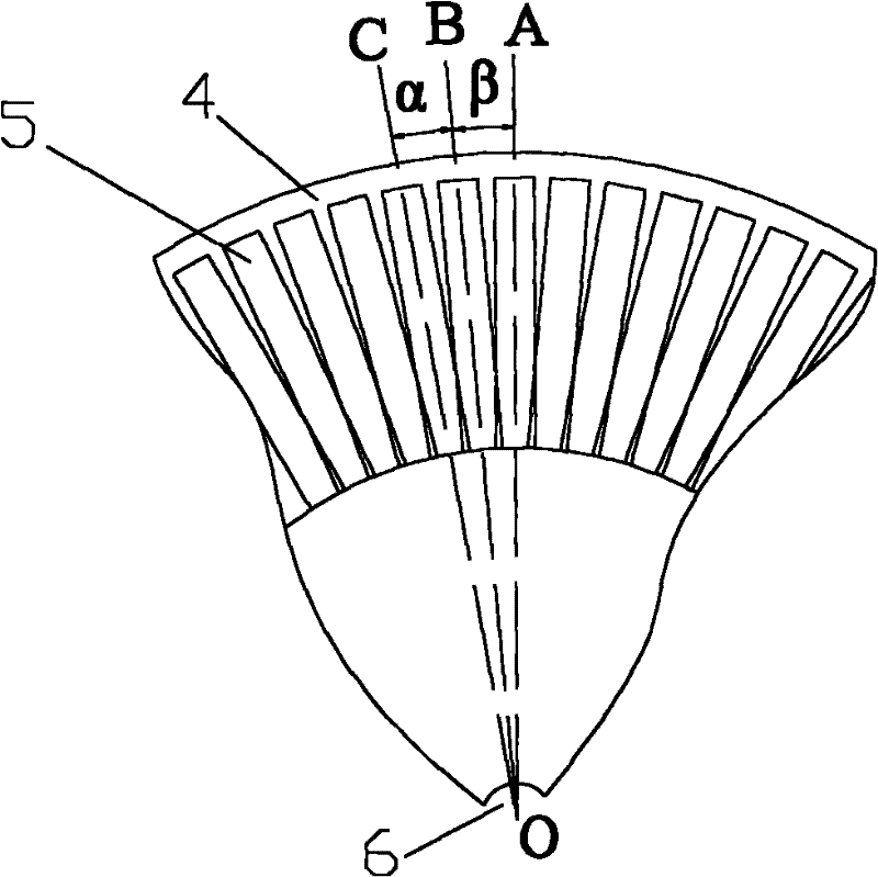
[0023] The present invention is composed of a computer 1 and more than two rotational speed acquisition units. figure 1 It is an embodiment composed of three rotational speed acquisition units. Wherein, the rotational speed acquisition unit includes a signal conditioning device 2, a sensing device 3 and a turntable 4, each turntable 4 is made of light-shielding materials, such as metal materials such as steel and aluminum, opaque plastics or other light-proof materials. Rectangular light-transmitting holes 5 are evenly distributed along the circumferential direction on the end surface of each turntable 4 , and the centerline of the rectangular light-transmitting holes 5 along the length direction passes through the center of the turntable 4 . Sensing device 3 can be such as Figure 7 The circuit shown is composed of groove optocouplers.

[0024] In each speed acquisition unit, the sensing device 3 is close to the rectangular light-transmitting hole 5 of the turntable 4, the ...


PUM


Abstract

The invention discloses a high-resolution rotation-speed measuring device. In each rotation-speed collecting unit, rectangular light-transmitting holes are evenly distributed on the end surface of a rotating disk along a circumferential direction, the rectangular light transmitting holes pass through a circle center of the rotating disk along a center line of a length direction, a sensing device approaches to the rectangular light transmitting holes of the rotating disk, the output end of the sensing device is connected with the input end of a signal conditioning device through a signal wire,the signal conditioning device is used for converting signals output by the sensing device into square signals, the output end of the signal conditioning device is connected with a computer through the signal wire; the end surfaces of the rotating disks in each rotation-speed collecting unit are mutually parallel, and a connecting wire of the circle centers of the rotating disks is a straight line and is perpendicular to the end surface of each rotating disk; on a projection plane which is perpendicular to the connection wire, an included angle is formed between the center line of the rectangular light-transmitting holes of the rotating disks along the length direction and an orthogonal projection on the projection plane, and the included angles of the adjacent orthogonal projections of the center line are equal and are greater than zero. The invention can ensure that the measurement resolution is increased exponentially.

Description

technical field [0001] The invention relates to a measuring device, in particular to a rotating speed measuring device. Background technique [0002] Rotational speed is an important physical quantity. Currently, the rotational speed measurement method used in engineering generally adopts a combination of magnetoelectric, Hall-type or photoelectric sensing devices and a turntable. However, the existing rotational speed measuring device has only a single turntable. In order to improve the measurement resolution, the existing technology is to increase the number of metal protrusions or the number of light-transmitting holes on a single turntable, and at the same time adopt a sensor device and a signal conditioning circuit with a higher processing speed. However, the number of metal protrusions or the number of light-transmitting holes on a single turntable cannot be infinitely increased due to volume limitations, and the processing speed of existing sensing devices and signal...

Claims


Application Information

Patent Timeline
Patent Type & Authority Patents(China)
IPC IPC(8): G01P3/486G01P3/481
Inventor 何文华李伟吕胤鼎曲振爱石伟熊树生
Owner ZHEJIANG UNIV
Why Eureka
Try Eureka