Device and method for aligning the position of plate-shaped parts

A part and plate shape technology, applied in positioning devices, machine tool parts, feeding devices, etc., can solve problems such as impossible parts

Inactive Publication Date: 2010-12-08
SCHULER AUTOMATION
View PDF1 Cites 20 Cited by
  • Summary
  • Abstract
  • Description
  • Claims
  • Application Information

AI Technical Summary

Problems solved by technology

and it is impossible to handle large quantities of parts in this way

Method used


Image

  • Device and method for aligning the position of plate-shaped parts
  • Device and method for aligning the position of plate-shaped parts
  • Device and method for aligning the position of plate-shaped parts

Examples


Embodiment Construction

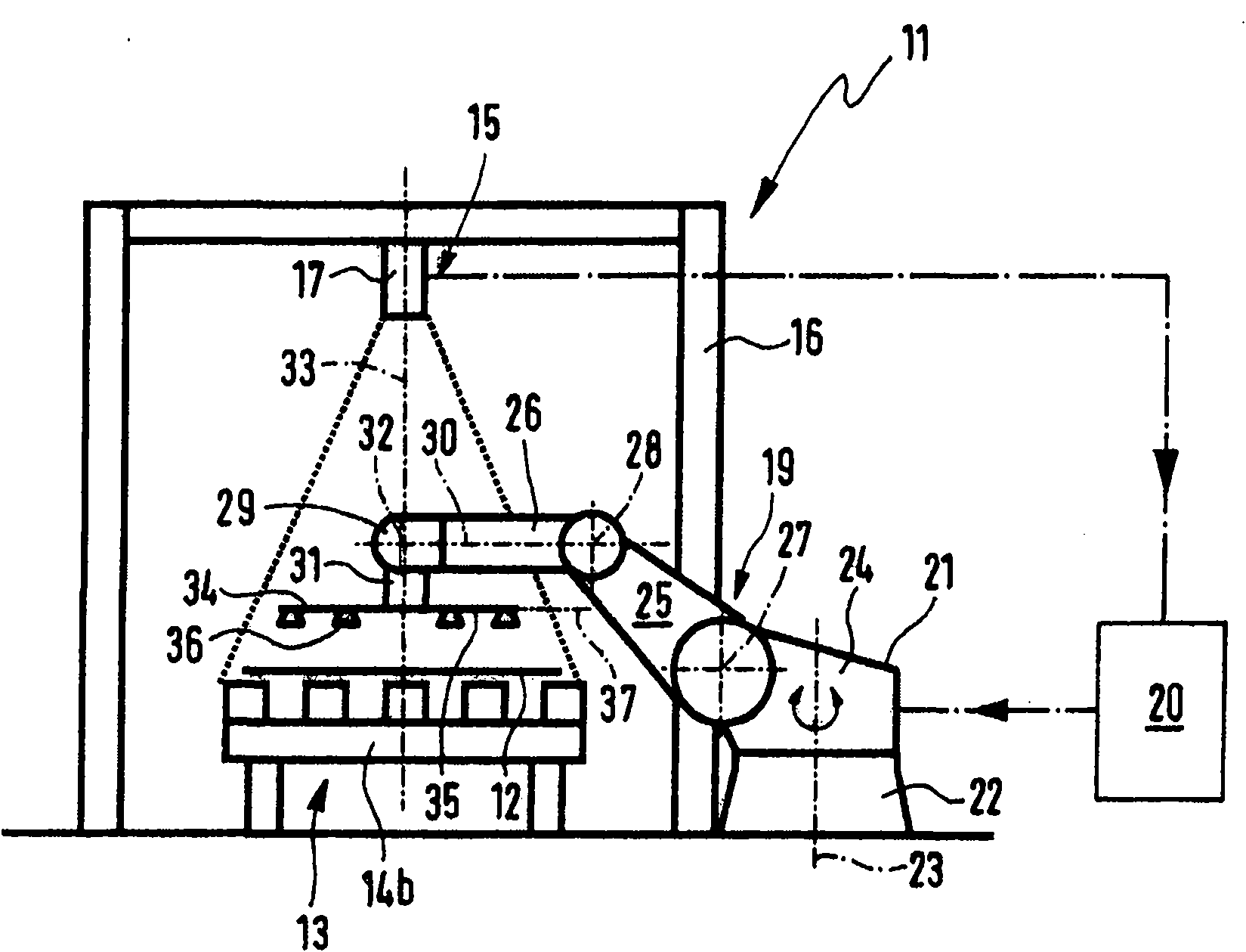
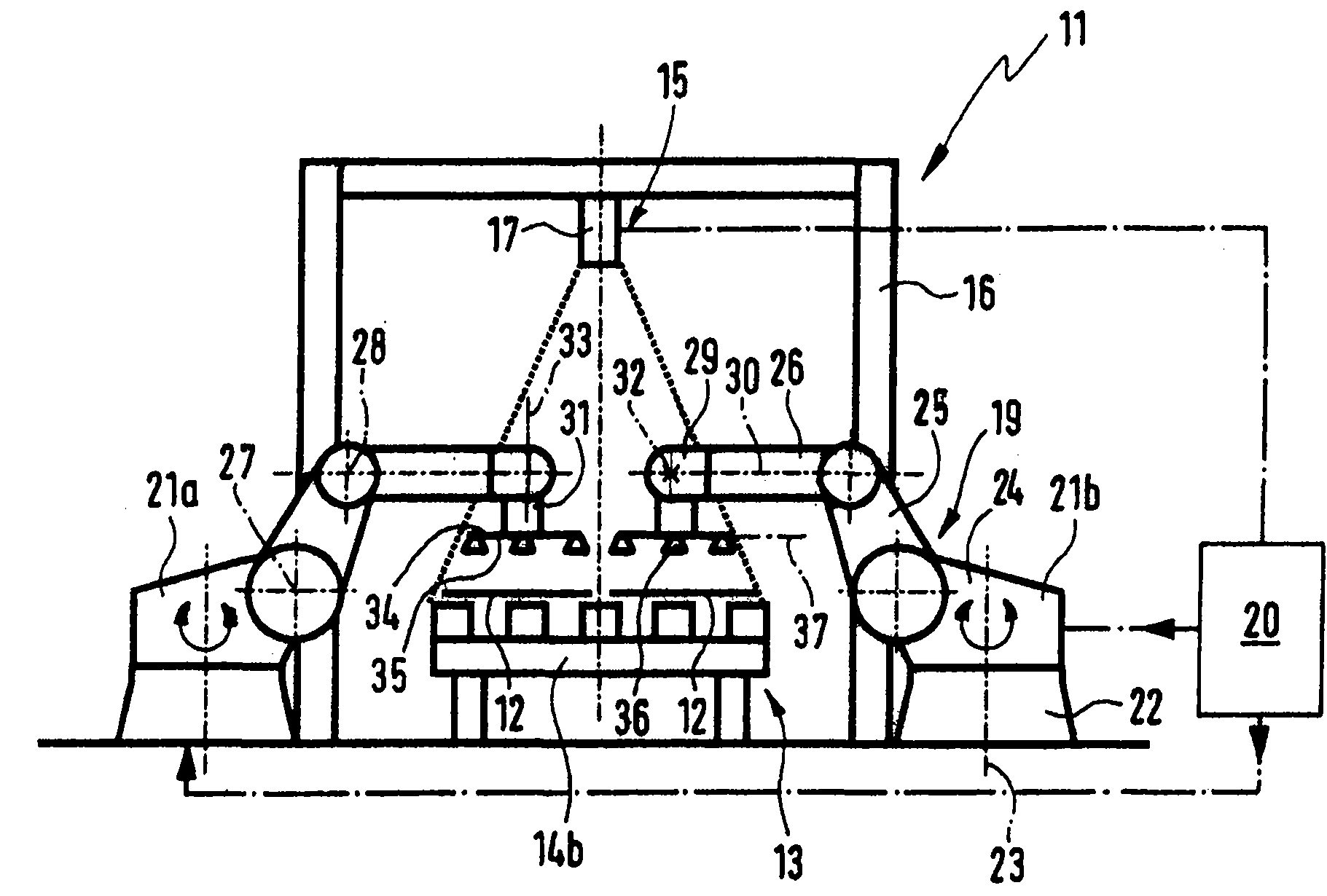
[0034] figure 1 with figure 2 A preferred embodiment of a device 11 according to the invention for positional positioning of a plate-shaped part 12 is shown. In this regard, the plate-shaped part 12 is a sheet metal blank, eg a body panel which has not yet been formed. The device for positioning, hereafter referred to simply as the positioning device 11, is part of a stamping line in which the plate-shaped part 12 finally reaches a metal forming press in which the plate-shaped part 12 is formed .

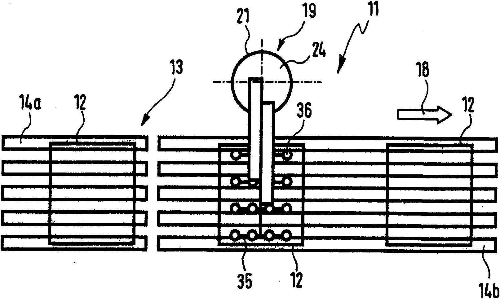
[0035] The position-locating device 11 comprises a continuous conveying device 13 for conveying the plate-shaped parts 12 . The continuous conveying device 13 comprises a plurality of corresponding conveyor belts 14a, 14b on which the plate-shaped parts 12 which have been previously depalletized or separated by a depalletizing device (not shown) are conveyed.

[0036] The position locating device 11 also includes an optical measuring device 15, suitably placed above one of the ...


PUM


Abstract

The invention relates to a device for aligning the position of plate-shaped parts (12), comprising a continuous conveyor device (13) for conveying plate-shaped parts (12), an optical measuring device that is associated with the continuous conveyor device (13) and that is used to determine the actual position of at least one specific plate-shaped part (12) and that compares the determined actual position to a stored desired position and determines the difference in the position of the actual position in relation to the desired position, a control device (20) that is coupled to the optical measuring device (15) for controlling a positioning unit (19) in such a manner that at least one specific plate-shaped part (12), the difference in position in relation to the desired position being determined, can be received on the receiving area by the positioning unit (19) and can be deposited on a defined depositing area in a precise position corresponding to the desired position, for further transportation on the continuous conveyor device (13).

Description

technical field [0001] The invention relates to a device for adjusting the position of plate-shaped parts, especially sheet metal blanks. Background technique [0002] In so-called press lines, high production capacities cannot be achieved unless the sheet metal blanks supplied by means of a continuous conveyor are transferred to the workstations, in particular the downstream metal forming presses, in the correct position, i.e. at defined set positions. In this context, a known method provides for determining the actual position of an arriving sheet metal blank by means of an optical measuring device and comparing this actual position with a stored set position. From the comparison between the actual value and the set value, the deviation from the set position is determined, which is moved to the set position by providing a processing unit, such as a robot, which grabs the sheet metal blank which deviates from the set position, And transfer it to the downstream workstation ...

Claims


Application Information

Patent Timeline
Patent Type & Authority Applications(China)
IPC IPC(8): B21D43/11B21D43/00
CPCB23Q2240/002B25J9/1697B21D43/105B25J9/0093B21D43/003B23Q7/18B25J9/0084B21D43/11Y10S901/07
Inventor R·多纳J·波蒂兹
Owner SCHULER AUTOMATION
Why Eureka
Try Eureka