Pycnometer

A technology of hydrometer and chamber, which is applied in the field of hydrometer to achieve the effect of improving accuracy

Inactive Publication Date: 2010-12-08
COMMISSARIAT A LENERGIE ATOMIQUE ET AUX ENERGIES ALTERNATIVES
View PDF3 Cites 7 Cited by
  • Summary
  • Abstract
  • Description
  • Claims
  • Application Information

AI Technical Summary

Problems solved by technology

Commonly used devices also prevent manipulation inside the shielded chamber in which the sample is located

Method used


Image

  • Pycnometer
  • Pycnometer
  • Pycnometer

Examples


Embodiment Construction

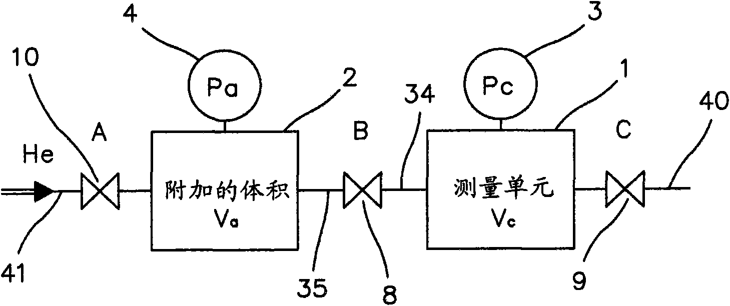
[0016] according to figure 1 , the system comprises a sample chamber 1, an expansion chamber 2, two pressure sensors 3 and 4 associated with chamber 1 and chamber 2, respectively. The chamber 1, the pressure sensor 3, and the communication pipe 34 between the valve 8 and the valve 10, and the chamber 2, the pressure sensor 4, and the communication pipe 35 between the valve 8 and the valve 10 constitute a gas network (réseau de gaz ). Conduits 40 and 41 enable the venting of valve 9 and the input of gas into the instrument, respectively. If V represents the volume of the sample placed inside sample chamber 1, V1 and V2 represent the volumes of chamber 1 and chamber 2, P1 and P2 represent the pressure of chamber 1 and chamber 2 before expansion, and PF represents the communication and The common pressure of these two chambers after expansion, then the following formula gives the sample volume: V=V1+[(PF-P2) / (PF-P1)]·V2.

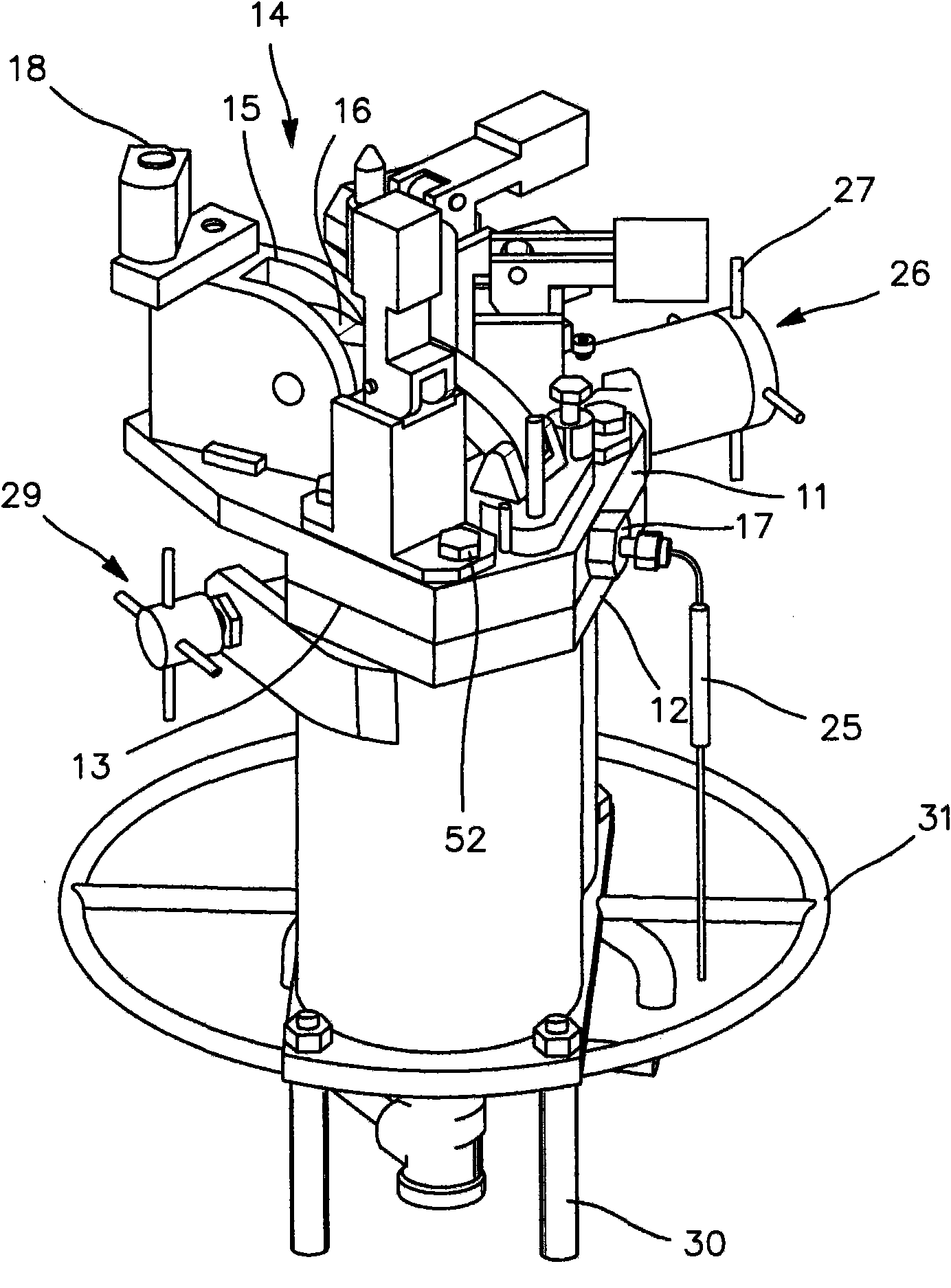
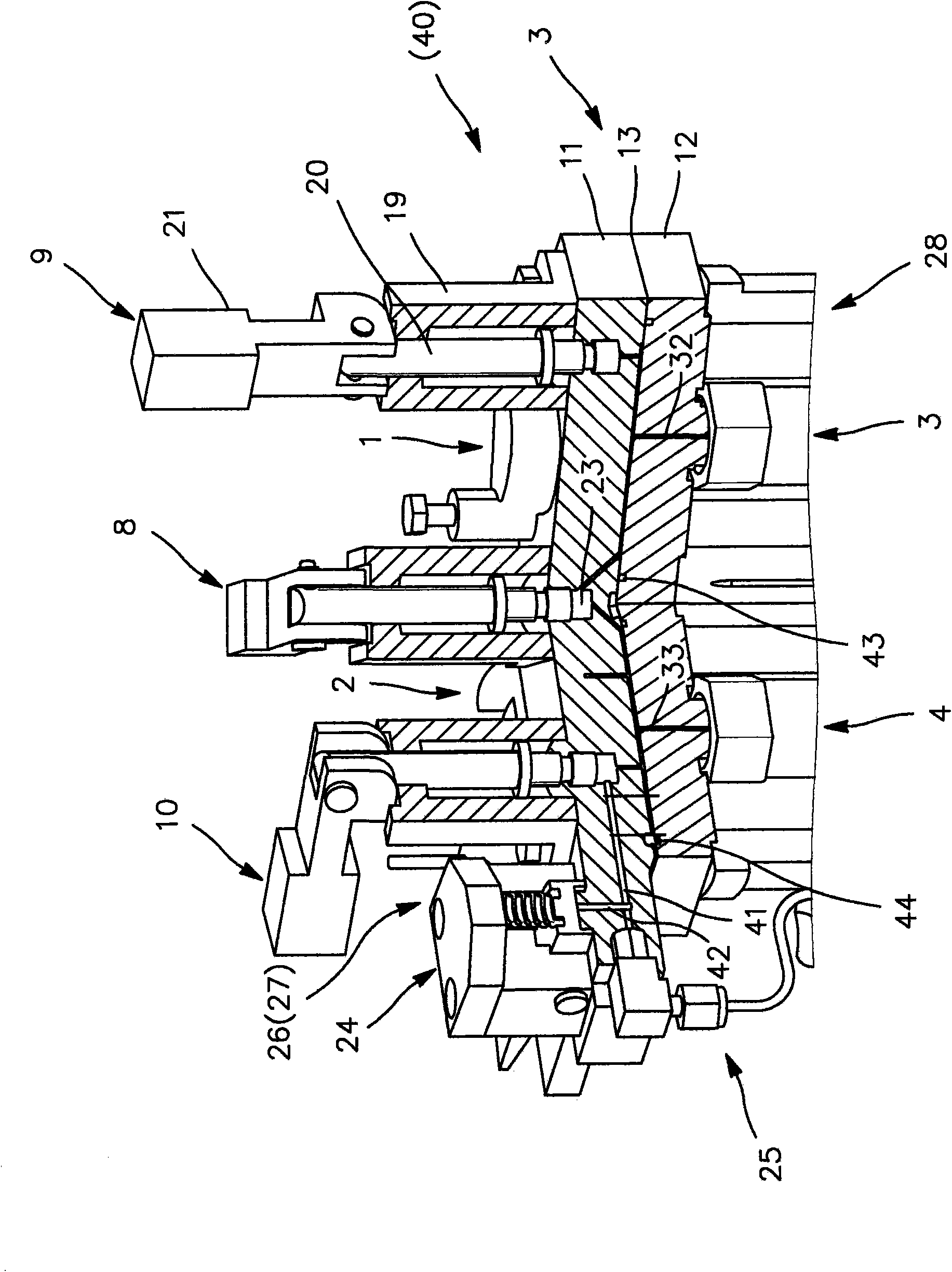
[0017] Now we continue to explain figure 2 , image...


PUM


Abstract

The invention relates to a device for measuring the volume of a sample, that comprises two cavities formed in a same block, pressure sensors (3, 4) mounted on the block and surrounded by a radiation shield (28) and connected to the sample chamber (1) by curved ducts. A temperature sensor (25) is also added. The apparatus can be used for measuring the volume of radioactive samples by gas expansion in an expansion chamber (2) without the radiations damaging the pressure sensors (3, 4) while allowing for the correction of temperature-rise effects.

Description

technical field [0001] The present invention relates to hydrometers, ie devices for measuring the volume of an object, called a sample, placed in a measuring chamber under gas pressure. Thus, the gas is designed to partially expand towards the expansion chamber in communication with the sample chamber. If the volumes of both chambers are known, the difference in the measured pressures can infer the volume of the sample. These treatments are particularly useful for determining the actual volume of porous objects that are readily permeable to gases. Together with the measurement of the mass of the sample, the volume indication enables the determination of the bulk density or density of the object composed of the sample. Background technique [0002] However, hydrometers are susceptible to inaccuracies caused in particular by the pressure sensor, the estimation of volume measurements, and the presence of dead volumes (static volumes) due to the chamber communicating with the ...

Claims


Application Information

Patent Timeline
Patent Type & Authority Applications(China)
IPC IPC(8): G01N9/02G01F17/00
CPCG01F17/00G01N2009/028G01N2033/0093
Inventor 弗雷德里克·若里翁克里斯托夫·布雷内斯弗拉维·波勒
Owner COMMISSARIAT A LENERGIE ATOMIQUE ET AUX ENERGIES ALTERNATIVES
Why Eureka
Try Eureka