Control method under dynamic soft reduction and determining method of reduction interval

A control method and a technology for determining the method, applied in the field of slab continuous casting technology, can solve the problems of reducing segregation, inability to precisely control the roll reduction, inability to control the reduction interval, etc., and achieve the effect of avoiding damage to the casting machine

Active Publication Date: 2013-07-17
田陆
View PDF0 Cites 7 Cited by
  • Summary
  • Abstract
  • Description
  • Claims
  • Application Information

AI Technical Summary

Problems solved by technology

[0004] At present, the fan section of most casting machines is integrated, and the pressing roller is installed on the upper frame and the lower frame of the fan section. The whole frame is controlled by four hydraulic cylinders to move up and down, and the roller cannot be controlled independently. Press down, so it will not be able to precisely control the roll to press down in the appropriate press down range
Even if the position of the liquid core calculated by the solidification model is very accurate and the control accuracy of the hydraulic cylinder is very high, the reduction interval cannot be well controlled within the range of the set solid phase ratio, and the reduction interval deviates too much from the set solid phase ratio , not only will not play a role in reducing segregation, but may also bring negative effects

Method used


Image

  • Control method under dynamic soft reduction and determining method of reduction interval
  • Control method under dynamic soft reduction and determining method of reduction interval
  • Control method under dynamic soft reduction and determining method of reduction interval

Examples


Embodiment Construction

[0026] The embodiments of the present invention will be described in detail below with reference to the accompanying drawings, but the present invention can be implemented in many different ways defined and covered by the claims.

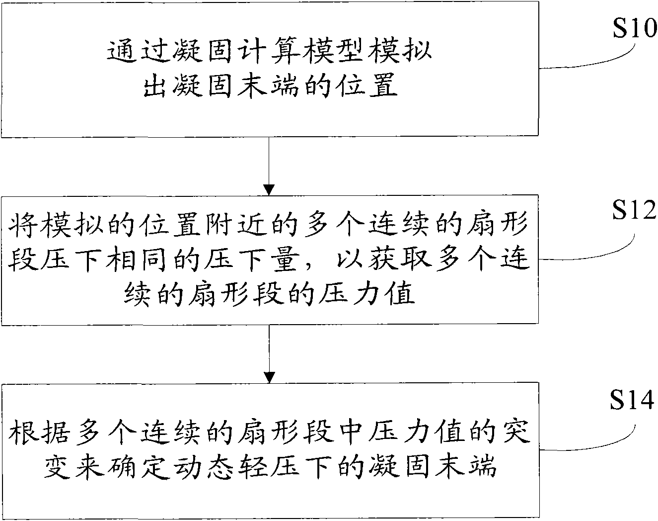
[0027] During the slab continuous casting process, a large amount of solutes with low melting point are enriched between the dendrites due to the effect of selective crystallization during the solidification process. The residual liquid enriched with impurities between the dendrites flows to the center and fills it, resulting in defects such as center segregation and center porosity of the slab. Based on this, it is considered that it is more appropriate to implement dynamic soft reduction within a distance close to the solidification end, rather than performing dynamic soft reduction at a position far away from the solidification end.

[0028] figure 1 A flow chart of the method for determining the light solidification end of continuous casting dy...


PUM


Abstract

The invention discloses a control method under dynamic soft reduction and a determining method of a solidified tail end and a reduction interval. The control method comprises the steps of: simulating the position of the solidified tail end through a solidifying computing model; carrying out pressure control on a sector of a continuous casting machine, wherein the pressure control comprises same reduction quantity of reducing a plurality of continuous sector near the simulated position, obtaining the pressure value of the continuous sectors; determining the position of the solidified tail end according to the mutation of the pressure value in the continuous sectors, determining the reduction interval according to the position of the solidified tail end; converting pressure control into position control after the reduction interval is determined, determining the reduction quantity of each sector of the reduction interval; and carrying out reduction control on each sector of the determined reduction interval according to the reduction quantity of each sector. The invention corrects the deviation caused by the solidifying computing model, and can effectively avoid the damage caused byreducing the continuous casting machine in a fully-solidified area according to the pressure values required by different types of steel in different positions.

Description

technical field [0001] The invention relates to a slab continuous casting process, in particular to a control method for continuous casting dynamic soft reduction, a method for determining the solidification end of a reduction interval, and a method for determining a reduction interval. Background technique [0002] For the slab formed by the continuous casting process, defects such as center segregation (composition segregation), center porosity, and centerline cracks are easily formed inside the slab. Since center segregation and center porosity cannot be eliminated by subsequent rolling or annealing treatment, and under high stress conditions, center segregation and center porosity are likely to cause delamination of the slab, so solving center segregation and center porosity is the key to improving slab quality an effective way. [0003] The soft reduction technology at the end of solidification is a new technology that is generally concerned by metallurgical researcher...

Claims


Application Information

Patent Timeline
Patent Type & Authority Patents(China)
IPC IPC(8): B22D11/16B22D11/12
Inventor 田陆赵磊
Owner 田陆
Why Eureka
Try Eureka