Hydraulic pressure type hot water recovery unit

A recovery device, hydraulic technology, applied in the field of hydraulic hot water recovery device, can solve the problems of potential safety hazards, waste of water resources, high power consumption, etc.

Inactive Publication Date: 2010-12-15
施成福
View PDF9 Cites 8 Cited by
  • Summary
  • Abstract
  • Description
  • Claims
  • Application Information

AI Technical Summary

Problems solved by technology

Although the electric heat tracing method solves the problem of freezing hot water pipes, but this method consumes more power and has potential safety hazards
The pipe emptying method is to release the hot water in the hot

Method used


Image

  • Hydraulic pressure type hot water recovery unit
  • Hydraulic pressure type hot water recovery unit
  • Hydraulic pressure type hot water recovery unit

Examples


Embodiment 1

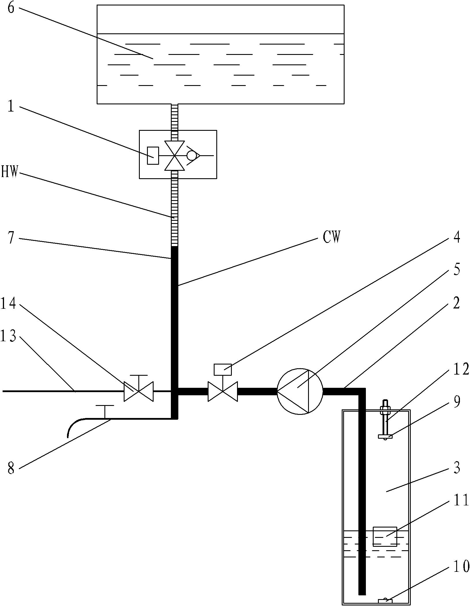
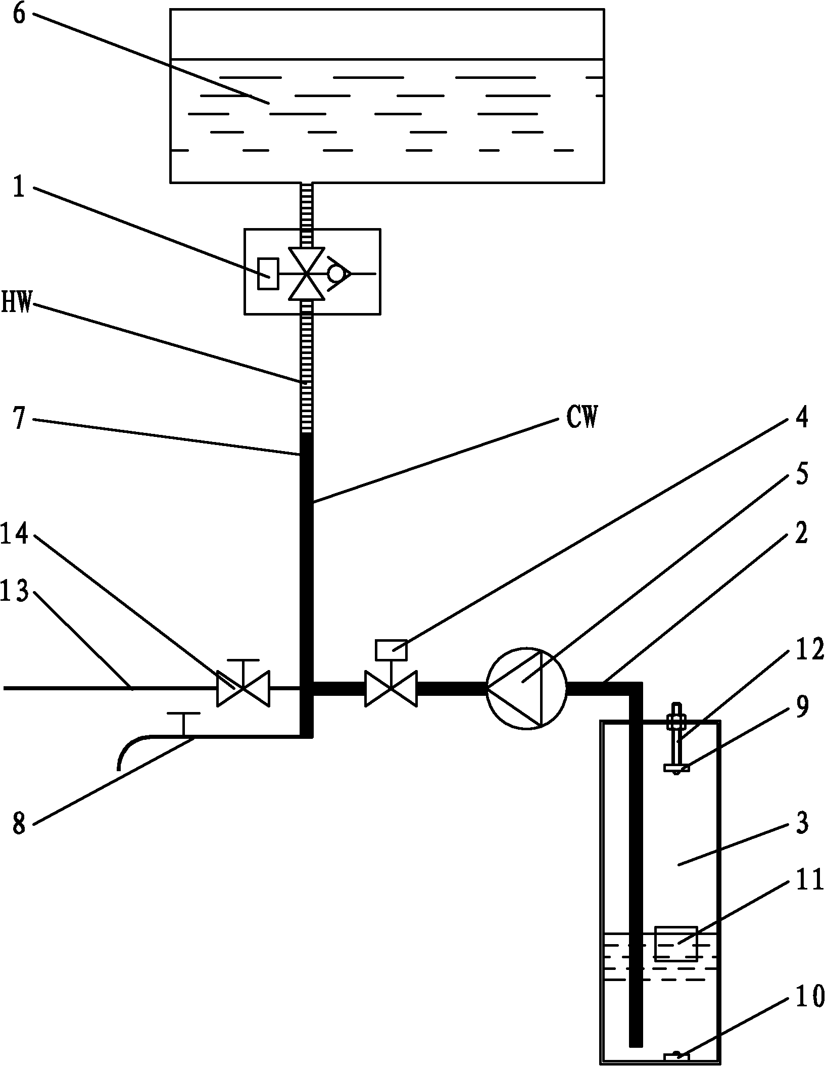
[0020] Such as figure 1 As shown, the hydraulic hot water recovery device of the present invention includes an emptying valve 1, a cold water pipe 2, a cold water tank 3, a cold water valve 4 and a water pump 5, and the emptying valve 1 includes three working ports, the first working port and the hot water The tank 6 is connected, the second working port is connected with the water outlet valve 8 through the hot water pipe 7, the third working port is connected with the outside atmosphere, and one end of the cold water pipe 2 is connected to the junction of the hot water pipe 7 and the water outlet valve 8, The other end is arranged in the cold water tank 3, and the water pump 5 and the cold water valve 4 are installed in series on the cold water pipe 2, and the water pump 5 adopts a centrifugal water pump with backflow characteristics. The cold water tank 3 is also externally connected with a water inlet pipe 13, and a water inlet valve 14 is also housed on the water inlet pi...

Embodiment 2

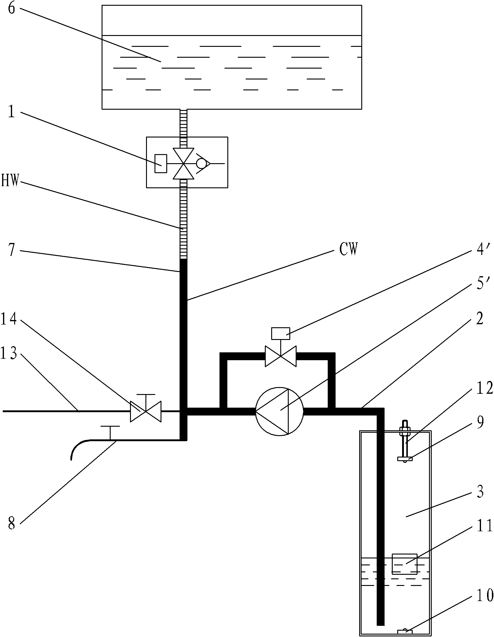
[0027] Such as figure 2 As shown, the difference between the second embodiment of the hydraulic hot water recovery device of the present invention and the first embodiment is that the cold water valve 4' and the water pump 5' are installed on the cold water pipe 2 in parallel, and the water pump 5' adopts different Screw pump, piston pump or diaphragm pump with reverse flow characteristic.

[0028] Its working process is also different from the first implementation method:

[0029] When the water outlet valve 8 is opened, the first working port and the second working port of the emptying valve 1 are connected, the third working port is closed, the cold water valve 4' and the water pump 5' are closed, and the hot water HW flows out from the water outlet valve 8;

[0030] When the water outlet valve 8 is closed, the cold water valve 4' is still closed. If hot water needs to be recovered, the water pump 5' is started, and the water pump 5' pumps the cold water CW in the cold wa...


PUM


Abstract

The invention discloses a hydraulic pressure type hot water recovery unit, relating to a water-saving frost crack resistant device and aiming at providing a hydraulic pressure type hot water recovery unit which has simple structure, saves water and energy and can prevent pipelines from frost crack. The recovery unit is composed of a blowoff valve, a cold water pipe, a cold water tank, a cold water valve and a water pump, wherein the blowoff valve comprises three working holes, the first working hole is communicated with a hot water tank, the second working hole is communicated with an outlet valve via a hot water pipe, and the third working hole is communicated with external air; one end of the cold water pipe is connected on the junction of the hot water pipe and the outlet valve, and the other end thereof is arranged in the cold water tank; the water pump and the cold water valve are arranged on the cold water pipe; and the cold water tank is internally provided with a water level sensing device. When the outlet valve is opened, the first working hole and the second working hole of the blowoff valve are communicated, and the cold water valve and the water pump are closed; when the outlet valve is closed, the cold water valve is opened, and the water pump is started; and when the water level sensing device senses a low water level, the water pump is closed, and the second working hole and the third working hole are communicated.

Description

technical field [0001] The invention relates to a water-saving antifreeze cracking device, in particular to a hydraulic hot water recovery device. Background technique [0002] Solar water heaters are generally composed of three parts: heat collectors, hot water tanks, and upper and lower water pipes. The heat collectors and hot water tanks are generally installed on the top floor of buildings, and the water outlet valve is connected to the user's home through a long hot water pipe. After the water outlet valve is closed for a period of time, the hot water retained in the hot water pipe will gradually become colder. After the user opens the water outlet valve again, it usually takes a period of cold water to flow out before hot water flows out. When the temperature is low in winter, the water remaining in the hot water pipe will also freeze and crack the hot water pipe. In order to prevent the hot water pipe from freezing and cracking, the current method is to install an ele...

Claims


Application Information

Patent Timeline
IPC IPC(8): F24J2/46
CPCY02E10/40
Inventor 施成福
Owner 施成福
Why Eureka
Try Eureka