Automatic optical inspection method for printed circuit board comprising resistance element
A technology of automatic optical inspection and printed circuit board, which is applied in the direction of material analysis, measuring devices, scientific instruments, etc. through optical means, and can solve problems such as poor promotion ability
- Summary
- Abstract
- Description
- Claims
- Application Information
AI Technical Summary
Problems solved by technology
Method used
Image
Examples
Embodiment Construction
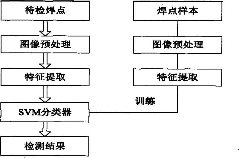
[0045] The flow chart of the method for detecting solder joints with resistance elements on printed circuit boards of the present invention is as attached figure 1 shown. Specifically, preprocessing and feature selection are performed on the solder joint image of the training sample first. After completing these two parts, the features of the solder joint image are input into the classifier for training. Finally, the same preprocessing and feature selection are performed on the solder joint image of the test sample, and the The test sample features are input into the classifier for classification.
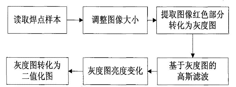
[0046] like figure 2 Shown is the solder joint image preprocessing flow chart. Since the size of the solder joint sample images is inconsistent, after inputting the image, all the solder joint images can be adjusted to the same length and width, so that it is easy to extract relevant features and information through standardized images . Then extract the red area and turn it i...
PUM
 Abstract
Description
Claims
Application Information
 - R&D
- Intellectual Property
- Life Sciences
- Materials
- Tech Scout
- Unparalleled Data Quality
- Higher Quality Content
- 60% Fewer Hallucinations
Browse by: Latest US Patents, China's latest patents, Technical Efficacy Thesaurus, Application Domain, Technology Topic, Popular Technical Reports.
© 2025 PatSnap. All rights reserved.Legal|Privacy policy|Modern Slavery Act Transparency Statement|Sitemap|About US| Contact US: help@patsnap.com


