Supercharge Your Innovation With Domain-Expert AI Agents!

Device and method for testing electric field-enhanced heat exchange performance in micro-channel

A technology for strengthening heat exchange and testing devices, applied in the field of microelectronics, can solve problems such as unfavorable and inability to study boiling phenomenon, and achieve the effect of good transparency

Inactive Publication Date: 2010-12-15
SHANGHAI JIAO TONG UNIV
View PDF5 Cites 4 Cited by
  • Summary
  • Abstract
  • Description
  • Claims
  • Application Information

AI Technical Summary

Problems solved by technology

However, in this prior art, since the side wall of the microchannel is made of silicon, the sides are opaque, and the growth, increase and detachment process of the boiling bubbles in the channel cannot be observed directly from the side wall of the microchannel, which is not conducive to the strengthening of the electric field in the microchannel. Research on heat transfer experiments; and limited by the principle of wet etching technology, the cross-section of the etched microchannel is isosceles trapezoidal. They are not parallel, but have a certain angle. The direction of the electric field in the microchannel is inconsistent with the direction of bubble growth, so it is impossible to study the boiling phenomenon under the condition that the direction of the electric field is the same as the direction of bubble growth.

Method used


Image

  • Device and method for testing electric field-enhanced heat exchange performance in micro-channel
  • Device and method for testing electric field-enhanced heat exchange performance in micro-channel
  • Device and method for testing electric field-enhanced heat exchange performance in micro-channel

Examples


Embodiment Construction

[0022] The embodiments of the present invention are described in detail below. This embodiment is implemented on the premise of the technical solution of the present invention, and detailed implementation methods and specific operating procedures are provided, but the protection scope of the present invention is not limited to the following implementation example.

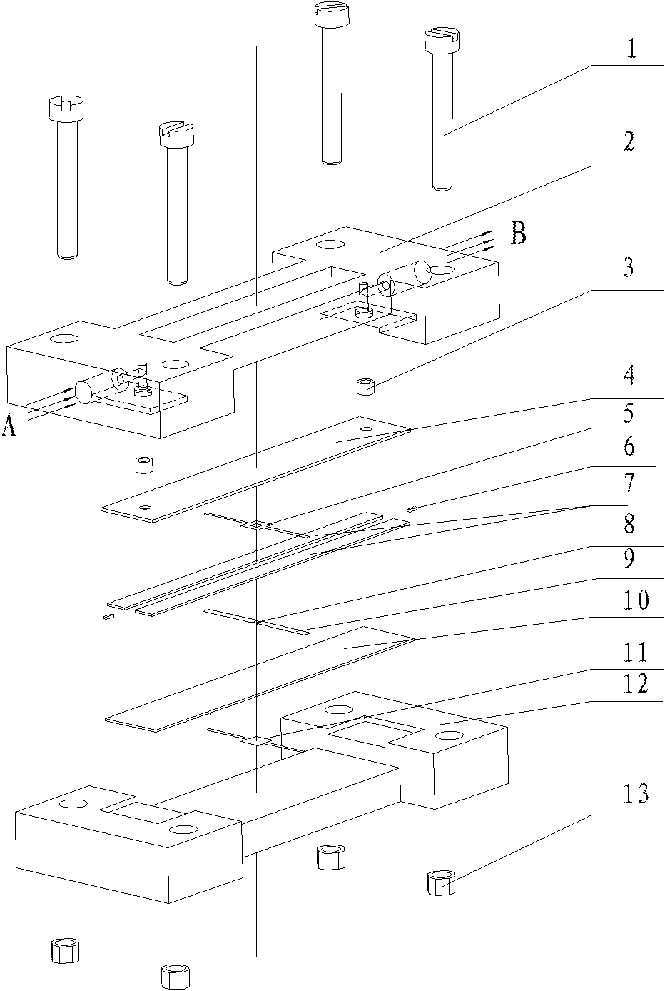
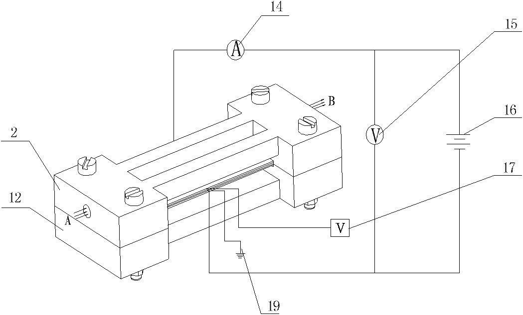
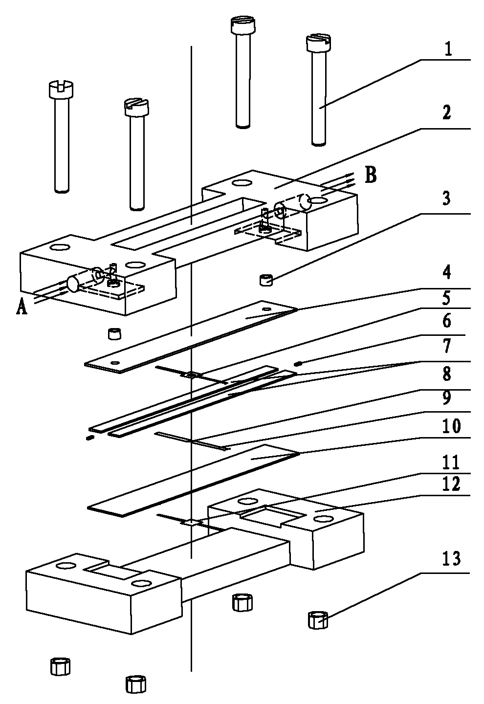
[0023] Such as figure 1 and figure 2 As shown, this embodiment includes: an upper clamping plate 2, a sealing rubber ring 3, an upper glass cover plate 4, an upper electrode 5, a side window 7, a micro heater 8, a micro heater lead wire 9, a lower glass cover plate 10, and a lower electrode 11. Lower splint 12, ammeter 14, voltmeter 15, drive power supply 16, test power supply 17, wherein: the micro heater 8 and the side window 7 are located between the two glass cover plates 4, 10, and the two electrodes 5, 11 are respectively Located on the inside of the two glass cover plates 4, 10, the two splints 2, 12 are ...


PUM

PropertyMeasurementUnit
Diameteraaaaaaaaaa
Thicknessaaaaaaaaaa
Thicknessaaaaaaaaaa

Abstract

The invention relates to a device and a method for testing electric field-enhanced heat exchange performance in a micro-channel, which belong to the technical field of microelectronics. The device comprises a pair of splints, a pair of glass cover plates, a pair of electrodes, a side view window, a micro-heater, an ammeter, a voltmeter, a driving power supply and a test power supply, wherein the micro-heater and the side view window are positioned between the two glass cover plates; the two electrodes are positioned on the lower surfaces of the two glass cover plates respectively; the two splints are fixedly arranged on the outer sides of the two glass cover plates respectively; the two ends of the micro-heater are connected in series with the ammeter and the driving power supply respectively; the voltmeter is connected in parallel to the two ends of the driving power supply; and the two electrodes are connected with the test power supply and the ground respectively. The direction of an electric field line of the device can be vertical to the surface of the micro-heater, the dynamic characteristic of boiling steam bubbles can be observed directly from a side face and an observation angle can be switched, so that the dynamic characteristic of the boiling steam bubbles in the micro-channel under electric field enhancement is observed more completely and contribution to researching the motion characteristic of the boiling steam bubbles under the action of an electric field is made.

Description

technical field [0001] The invention relates to a device and a testing method in the field of microelectronic technology, in particular to a testing device and a testing method for electric field enhanced heat transfer performance in a microchannel. Background technique [0002] In recent years, as the assembly density of electronic equipment has become higher and higher, and the power of electronic components has increased, higher requirements have been put forward for the methods and means of enhancing heat transfer in microchannels. The method of applying an electric field in microchannels To enhance heat transfer is a new way to enhance heat transfer. [0003] The Lift-off process refers to the MEMS metal preparation method realized by preparing a sacrificial layer with the same shape as the target material in the substrate. This technology is superior to the existing etching preparation method and can be applied to the preparation of Meter-level semiconductor equipment...

Claims


Application Information

Patent Timeline
IPC IPC(8): G01N25/20
Inventor 高明郑平全晓军陈钢章任蕾
Owner SHANGHAI JIAO TONG UNIV
Features
  • R&D
  • Intellectual Property
  • Life Sciences
  • Materials
  • Tech Scout
  • Unparalleled Data Quality
  • Higher Quality Content
  • 60% Fewer Hallucinations
Learn More