LED display screen

A technology for LED displays and circuit substrates, applied in lighting devices, light sources, instruments, etc., can solve the problems of inability to arrange components, small pixel pitch, and rising costs, eliminate graininess and dazzling feeling, and reduce the area of ​​dark areas , the effect of improving uniformity

Inactive Publication Date: 2010-12-15
GUANGDONG VTRON TECH CO LTD
View PDF3 Cites 7 Cited by
  • Summary
  • Abstract
  • Description
  • Claims
  • Application Information

AI Technical Summary

Problems solved by technology

Especially when viewed at a close distance (such as indoors), the picture will appear incoherent and incomplete, seriously affecting the viewing effect
[0006] (2) The screen has a strong sense of glaring
But in this way, the pixel arrangement density will be increased, which will greatly increase the cost
[0009] On the other hand, in the high-pixel-density LED display screen with more market demand, such as a display screen with a pixel pitch of 4mm made of Φ2mm LEDs, since the pixel density itself is already quite high, if the method of increasing the pixel density is used to reduce the particle size If there is a sense, you will encounter the bottleneck of circuit board arrangement, and you will not be able to arrange components; at the same time, due to the small pixel pitch, the shading edge cannot be installed and fixed, and the traditional method cannot be implemented on high-pixel-density LED displays.
At present, although the industry has proposed to use special LED components or irregular special-shaped LED components to improve the luminous effect of components in order to achieve the purpose of reducing graininess, but due to processing technology problems and high cost, it cannot be implemented.

Method used


Image

  • LED display screen
  • LED display screen
  • LED display screen

Examples


Embodiment approach 1

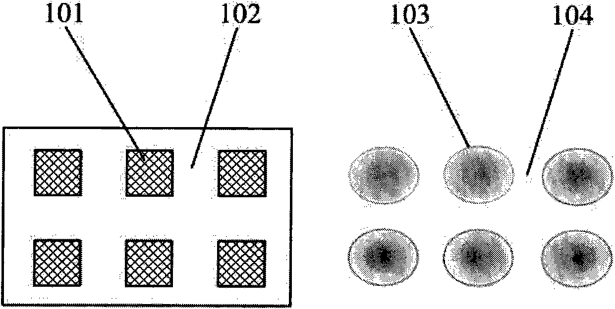
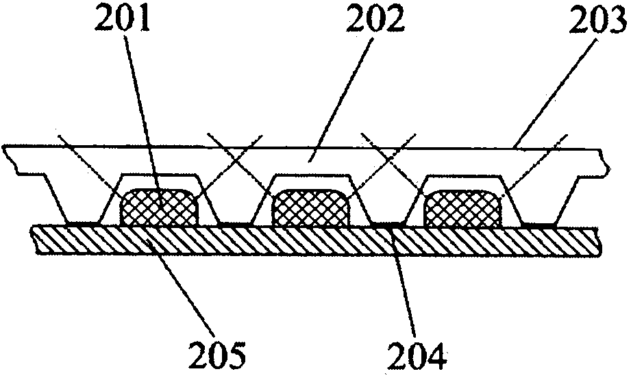
[0029] like figure 2 As shown, the LED display screen of this embodiment includes a circuit substrate 205 , several LED elements 201 distributed on the circuit substrate 205 , and a light mixing device arranged on the circuit substrate 205 .

[0030] The light mixing device is a transparent plate 202 , on one side of the transparent plate 202 there are several grooves matched with the several LED elements 201 . The groove is flared, and the shape can be a trapezoidal arc, etc., and its flared end is set toward the circuit substrate 205 , that is, the groove is upside down on the circuit substrate 205 , and there is at least one LED element 201 in the groove.

[0031] The flaring end of the groove is fixedly connected with the circuit substrate 205 through glue 204 . The transparent plate 202 can be fixed on the circuit substrate 205 by bonding, or can be fixed on the circuit substrate 205 by screws when the space is large. In this embodiment, the groove serves as a diffusio...

Embodiment approach 2

[0039] like Figure 4 As shown, the difference between the present embodiment and the first embodiment lies in the light mixing device. The light mixing device in this embodiment is a planar component 402 , and the planar component 402 is distributed with flaring holes matched with the LED elements 401 on the circuit substrate 405 . The narrow end of the flaring hole is fixedly connected with the circuit substrate 405 through glue 404 .

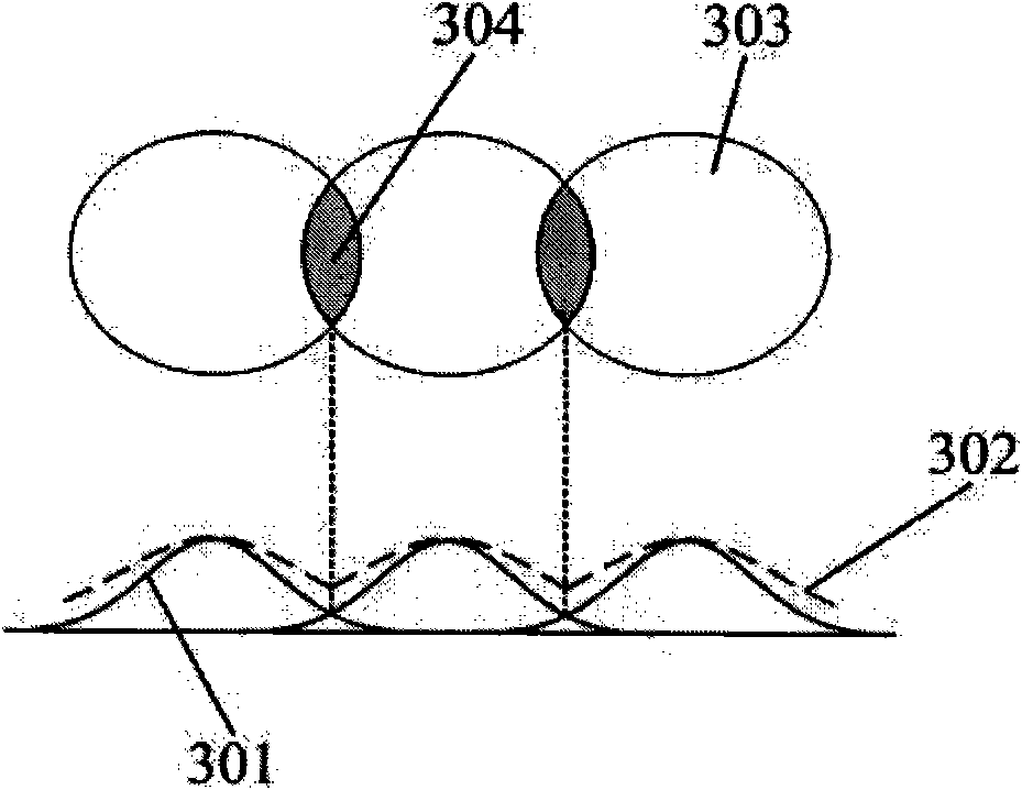
[0040] In addition, in order to enhance the diffusion effect, a color mixing agent can be coated in the flaring hole to make it opaque, so that the light is reflected in the cavity and superimposed with the edge light of the adjacent LED element 401, so as to achieve the purpose of light mixing. Regardless of whether the planar component 402 is made of a transparent material or a non-transparent material such as engineering plastics, a color mixing agent can be coated in the flaring hole to enhance the color mixing effect. In this embodimen...


PUM


Abstract

The invention relates to an LED display screen which comprises a circuit substrate and a plurality of LED elements distributed and arranged on the circuit substrate. In addition, the LED display screen further comprises a light-mixing device arranged on the circuit substrate; the light-mixing device comprises a plurality of diffusion cavities; and each diffusion cavity is provided with at least one of the LED elements. By the invention, LED lights are scattered by adopting the diffusion cavities of the light-mixing device, the light-emitting region and the light-mixing region of an LED are enlarged, and the area of the dark region is reduced. Therefore, the granular sensation and the glaring sensation of the pixels are decreased or eliminated, and the uniformity of the picture brightness is improved. Moreover, with the mode, the arrangement density of the LED elements cannot be increased, special LED elements are not needed to be designed and manufactured, ordinary LED elements are directly used, and the cost is relatively low.

Description

technical field [0001] The invention relates to an LED display screen. Background technique [0002] The full-color LED display is an image display system composed of a large number of three-color LEDs (light-emitting diodes). According to different installation occasions, it is divided into two categories: indoor screen and outdoor screen. Due to the long viewing distance of outdoor screens, the pitch of light-emitting elements (pixel pitch) is relatively large; the pixel pitch of indoor screens is smaller than that of outdoor screens. With the continuous improvement of people's pursuit of display effect and the continuous improvement of technology, the pixel pitch of LED display has been gradually reduced from 20mm, 18mm to 4mm, 3mm or even smaller. Regardless of whether it is an outdoor screen or an indoor screen, the pixel layout schematic diagram is as follows figure 1 shown. The LED elements 101 are neatly and orderly arranged on the circuit board 102 according to ...

Claims


Application Information

Patent Timeline
Patent Type & Authority Applications(China)
IPC IPC(8): G09F9/33F21V5/08F21Y101/02
Inventor 李军明刘志文
Owner GUANGDONG VTRON TECH CO LTD
Why Eureka
Try Eureka