Compound cyclone separator of dust collector

A cyclone separation device and composite technology, applied in the direction of suction filter, etc., can solve the problems of difficult cleaning, low separation efficiency, unsanitary dust, etc., and achieve the effect of good separation effect, high separation efficiency and compact structure

Inactive Publication Date: 2010-12-22
LG ELECTRONICS (TIANJIN) APPLIANCES CO LTD
View PDF0 Cites 10 Cited by
  • Summary
  • Abstract
  • Description
  • Claims
  • Application Information

AI Technical Summary

Problems solved by technology

[0010] 1. During the dust separation process, a relative vacuum gap area is formed between the swirl flow generator in the cyclone separator and the cone of the conical filter. When the rotation force of the light garbage is not enough, it is easy to enter this vacuum area. Light garbage such as paper scraps, fibers, and pet hair are easily entangled and blocked on the end surface of the cyclone generator or the outer bottom surface of the cone filter, making it unhygienic for users to dump dust, and it is very troublesome to clean and clean
[0011] 2. The cyclone separator in the prior art only has an elliptical barrel structure and a conical filter to separate and filter the dust, so the separation effect is often poor for some fine dust, the separation efficiency is low, and the filter is easy to be blocked
Greatly limit the use of occasions
Moreover, the structure of the swirling dust collection device in the prior art is complex and difficult to clean

Method used


Image

  • Compound cyclone separator of dust collector
  • Compound cyclone separator of dust collector
  • Compound cyclone separator of dust collector

Examples


Embodiment Construction

[0056] The present invention will be described in detail below with reference to the drawings and examples. In the drawings of the present invention, the same components as those in the prior art use the same symbols.

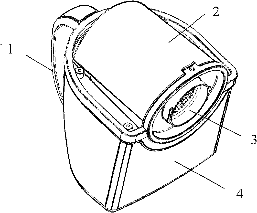
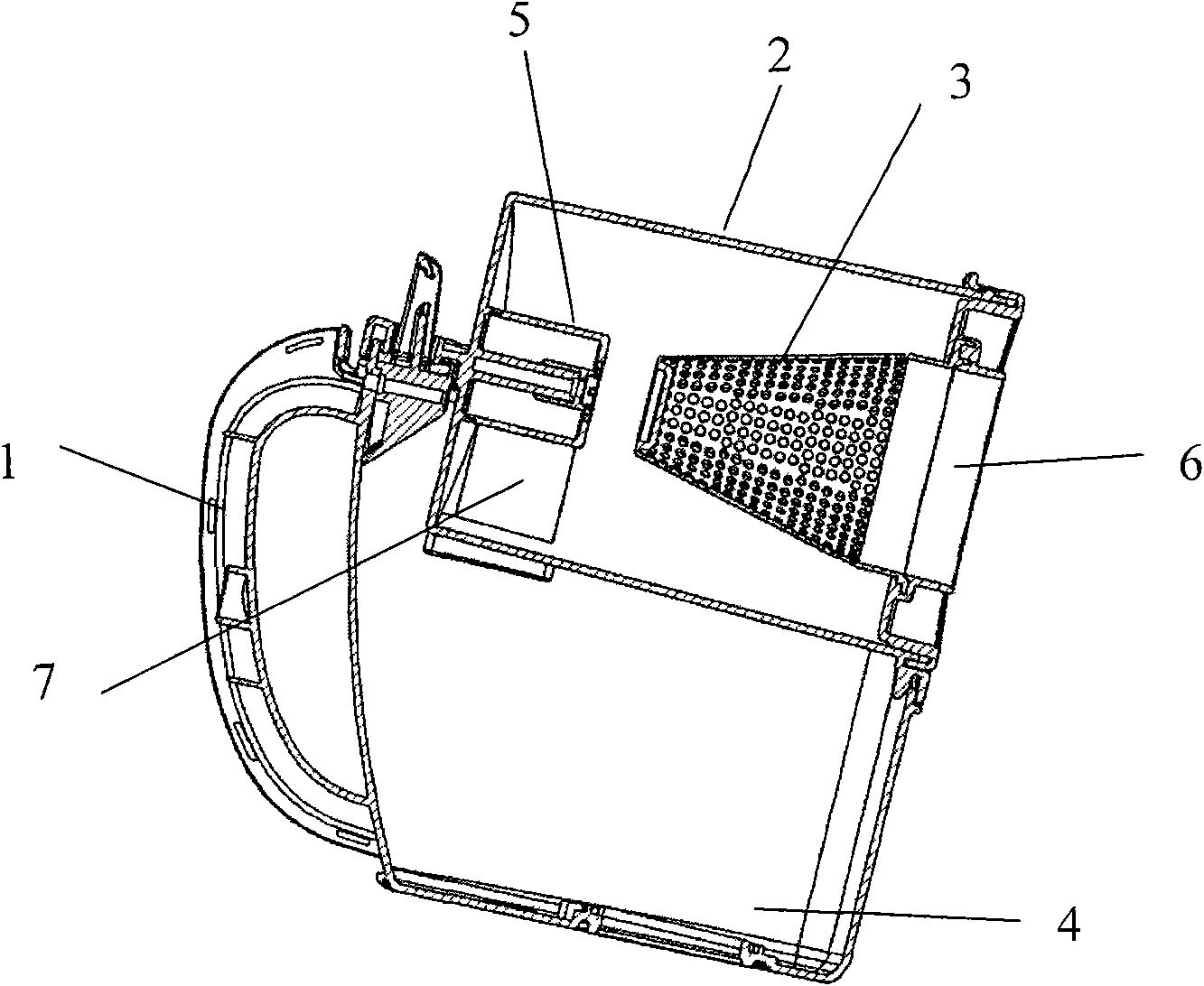
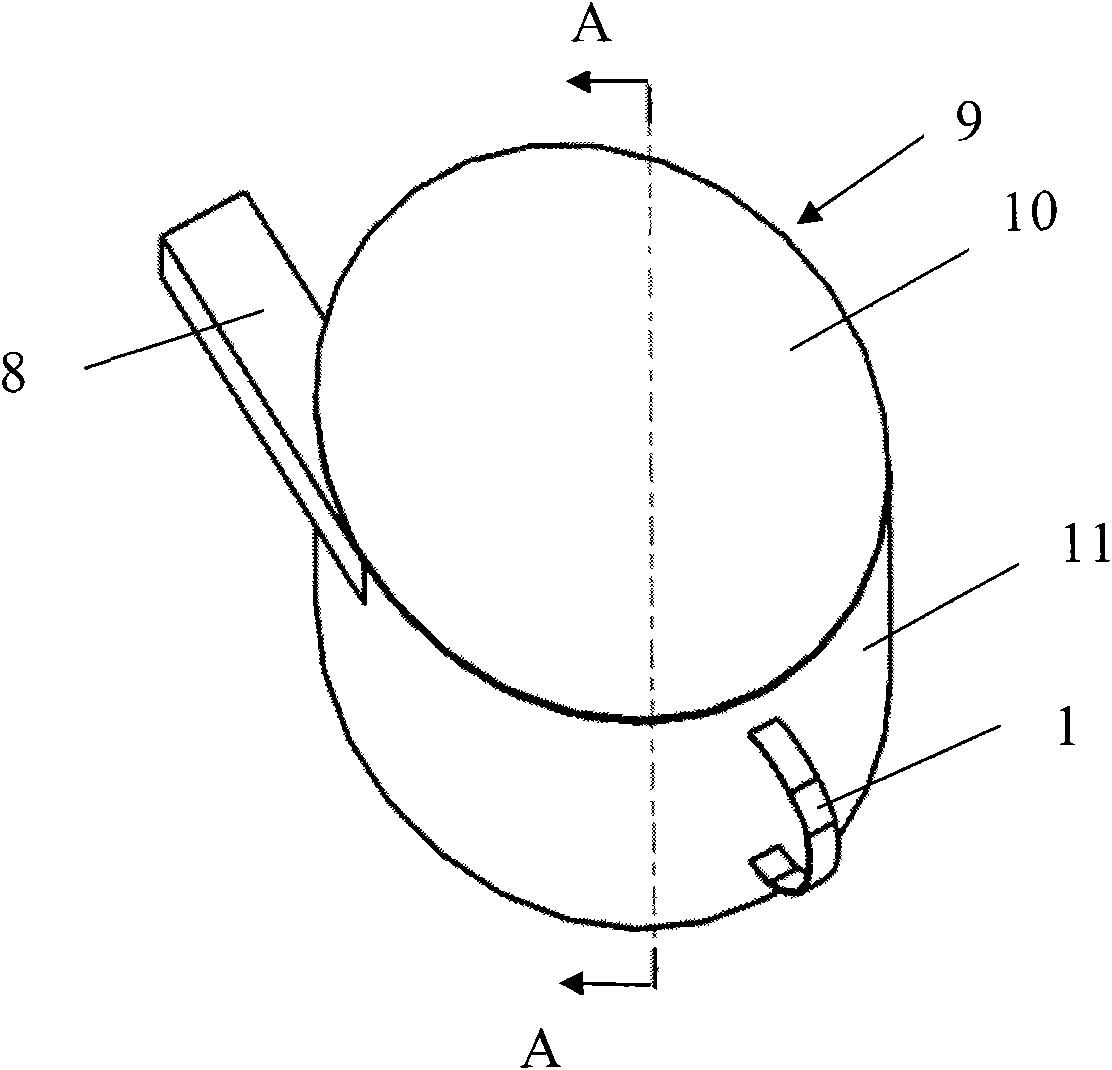
[0057] The composite cyclone separation device of vacuum cleaner of the present invention, as image 3 , Figure 4 , Figure 5 as shown, image 3 It is a perspective view of the appearance of the composite cyclone separation device of the vacuum cleaner of the present invention; Figure 4 It is the internal structure diagram of the composite cyclone separation device of the present invention with the upper cover removed; Figure 5 It is an internal structure diagram viewed from another angle without the upper cover of the present invention.

[0058] The composite cyclone separation device 9 of the vacuum cleaner of the present invention consists of a handle 1, a gas inlet 8, an elliptical separation structure 11 provided with a handle and an upper part wit...


PUM


Abstract

The invention provides a compound cyclone separator of a dust collector, comprising a handle, an air inlet, an elliptical separating structure provided with the handle and the air inlet at the upper part thereof, a round separating structure arranged above the center of the elliptical separating structure, an upper cover connected with the upper end of the round separating structure, a conical filter arranged in the center of the round separating structure, and a vent pipe which is connected at the lower end of the conical filter and extends out of the elliptical separating structure, wherein the round separating structure is composed of a drum and a drum bottom, the drum is provided with an air intake and a dust outlet; the elliptical separating structure is composed of a vertically arranged elliptical cylinder body and an elliptical cylinder body bottom with a central hole; and a coarse dust collecting part is formed between the drum and the elliptical cylinder body, and a fine dust collecting part is formed between the baseplate of the coarse dust collecting part and the elliptical cylinder body bottom. The invention can perform coarse dust separation on gases containing dust, thus avoiding that the conical filter is wound and blocked by light garbage. In addition, the invention has good separation effect for fine dust, compact structure and small volume.

Description

technical field [0001] The invention belongs to the field of vacuum cleaners, and in particular relates to a composite cyclone separation device with a multi-layer dust separation structure, which can separate dust multiple times, has good separation effect, compact structure and small volume. Background technique [0002] Vacuum cleaner is a kind of household appliance for indoor cleaning and sanitation, which is used to remove dust from floors, carpets, walls, furniture, clothing and various gaps. Generally speaking, a vacuum cleaner mainly includes a suction device and a suction pipeline. The suction device mainly formed by a motor and a fan is arranged in the body. The suction pipeline includes a suction head and a suction pipe. The air port communicates with the air inlet in the body through the telescopic tube and flexible pipe of the suction pipe. When the vacuum cleaner is running, the motor drives the impeller of the fan to rotate at a high speed, exhausting the ai...

Claims


Application Information

Patent Timeline
Patent Type & Authority Applications(China)
IPC IPC(8): A47L9/16
Inventor 肖宗亮
Owner LG ELECTRONICS (TIANJIN) APPLIANCES CO LTD
Why Eureka
Try Eureka