Automobile front body structure

A technology for the front of the body and the front and rear of the body, applied in the directions of the upper structure, the lower structure, the upper structure sub-assembly, etc., can solve the problems of difficulty in setting up extensions, inability to transmit collision loads to the other side, and inability to obtain buffer space, etc. To achieve the effect of improving the energy absorption effect

Inactive Publication Date: 2010-12-22
HONDA MOTOR CO LTD
View PDF4 Cites 0 Cited by
  • Summary
  • Abstract
  • Description
  • Claims
  • Application Information

AI Technical Summary

Problems solved by technology

That is, with this structure, it is difficult to install the above-mentioned extension in a narrow space, and even if the above-mentioned extension is installed, it is impossible to obtain a sufficient buffer space
[0009] In addition, although it is conceivable to soften the bumper beam itself to absorb the impact load, in the event of a deflection collision, that is, the impact load acts only on the left and right sides of the vehicle. On one side, since the bumper beam also has the function of transmitting the collision load to the other side, if the bumper beam itself is softened, it will not be able to transmit the collision load to the other side, so that the body on the hit side will appear Problems with large deformations

Method used


Image

  • Automobile front body structure
  • Automobile front body structure
  • Automobile front body structure

Examples


Embodiment Construction

[0036] Next, embodiments of the present invention will be described with reference to the drawings. However, the drawings should be read according to the orientation of the symbols in the drawings.

[0037] 【Example】

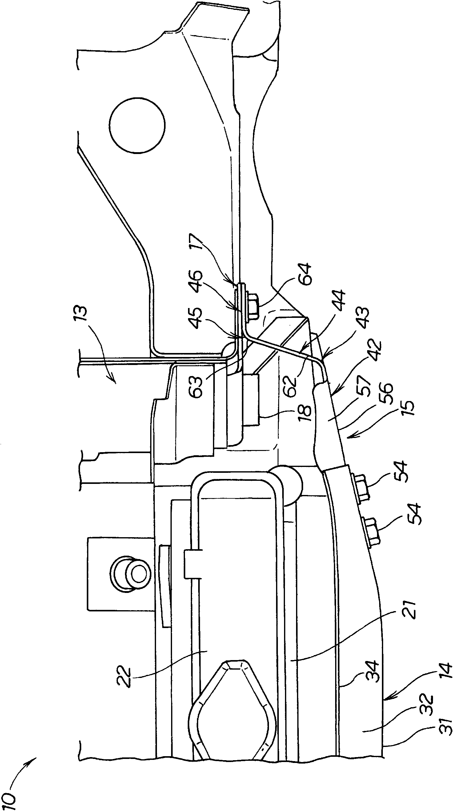
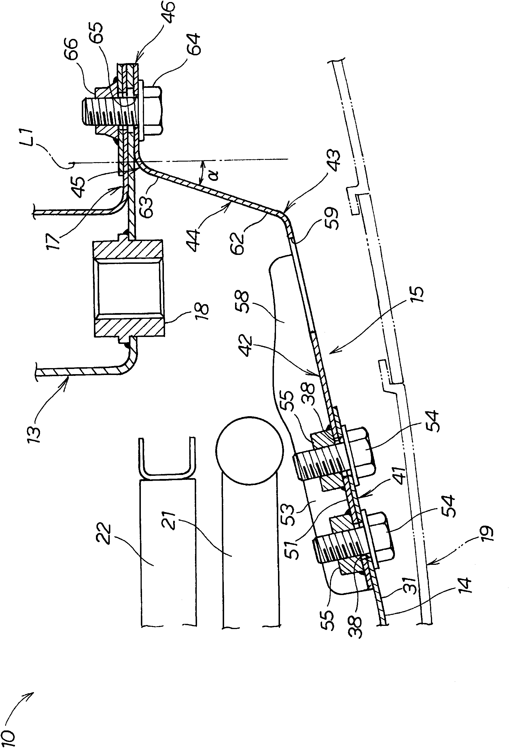
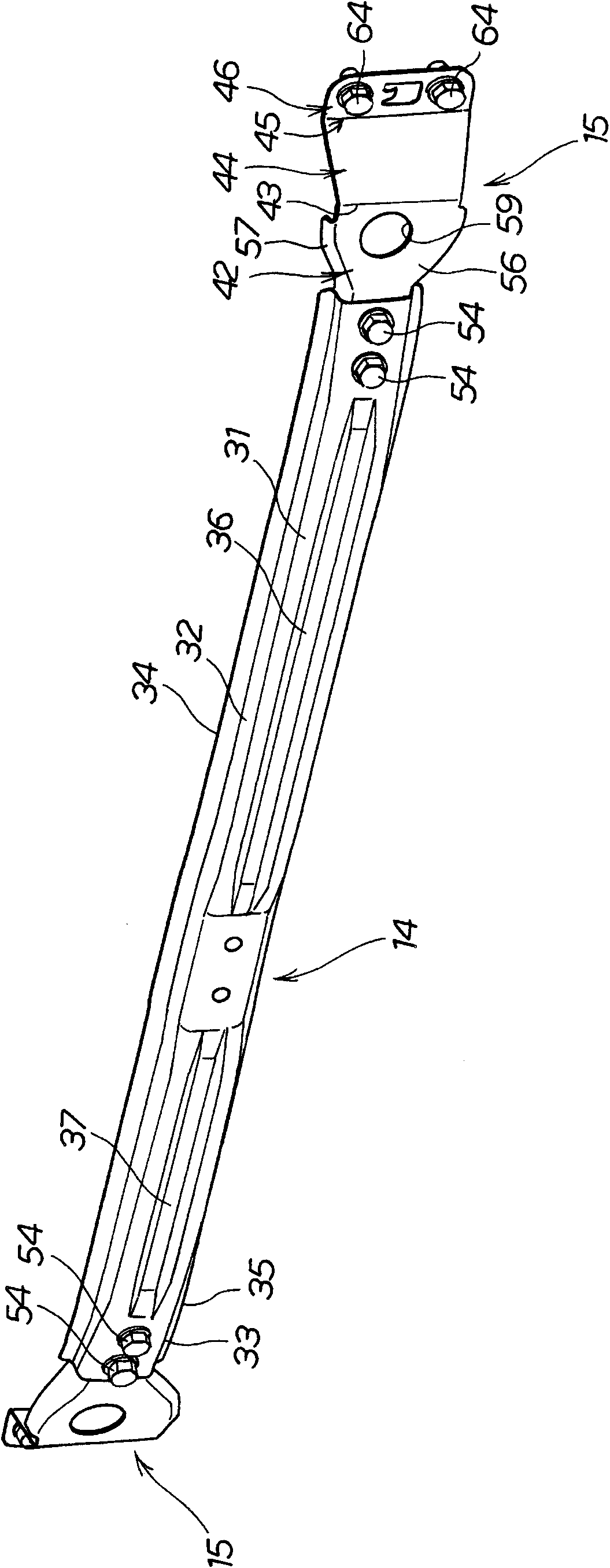
[0038] like figure 1 , figure 2 As shown, the vehicle body side structure 10 includes: a pair of side beams 13 (only one of which is shown in the figure) extending along the front and rear directions of the vehicle body; Beam 13 on.

[0039] The side beam 13 includes: beam side flange 17, which is used to install the low rigidity member 15 on the outside of the side beam 13 in the vehicle width direction; nut 18, which is used to install the tow hook 61 (refer to Figure 5 ).

[0040] Specifically, the high-rigidity part 14 is a bumper beam, and the low-rigidity part 15 is an extension that is located between the bumper beam 14 and the beam-side flange 17 of the side beam 13 .

[0041] Also, in the vehicle body side structure 10, a bumper fascia 19 is pro...


PUM


Abstract

The present invention provideS a vehicle front body structure, which is capable of performing a sufficient impact energy absorbing function even when it is employed in a vehicle that is hard to provide a large space between the front end of a front side frame and a bumper face. The vehicle front body structure includes a pair of side frames (13) extending in a longitudinal direction of the vehicle body, and a high-rigidity plate member (14) is disposed forwardly of front ends of the side frames (13) and extends in a width direction of the vehicle body, characterized in that the high-rigidity plate member is connected via a low-rigidity plate member (15) to side frames (13), the low-rigidity plate member has a rigidity smaller than a rigidity of the high-rigidity plate member and composed of sheet, wherein the low-rigidity plate member includes a transverse wall (42) connected to the high-rigidity plate member and extending in the width direction of the vehicle body, and a longitudinalwall (44) extending from the transverse wall to the side frames by a first bent portion (43) in the longitudinal direction of the vehicle body. When the high-rigidity plate member is subjected to a collision load, the low-rigidity plate member is deformable to start distorting at the bent portion to thereby absorb the collision load.

Description

technical field [0001] The present invention relates to a vehicle body front structure having an extension between a bumper beam and a front side member thereof for absorbing impact loads of the vehicle body front. Background technique [0002] In the prior art, body front structures are known which have a bumper beam which is supported via extensions on the front side members. [0003] The design requirement of the above-mentioned front structure of the vehicle body is that when a slight collision occurs, the extension parts are required to be crushed, while the main frame parts such as the front side beams cannot be deformed. [0004] As one of the vehicle body front structures that can meet the above-mentioned design requirements, there is known a vehicle body front structure having a structure in which the front end portions of the front side members and the front end portions of the lower members are connected to each other, and by the connected The front end supports ...

Claims


Application Information

Patent Timeline
Patent Type & Authority Applications(China)
IPC IPC(8): B60R19/42B62D25/02
CPCB60D1/52B60D3/00B60D1/565B60D1/04B60R19/26B60D1/485B60D1/488B62D25/082B60R19/34B62D21/152
Inventor 柏木正和高桥浩二
Owner HONDA MOTOR CO LTD
Why Eureka
Try Eureka