
Balance shaft module

A technology for balancing shafts and crankcases, which is used in engine lubrication, mechanical equipment, pressure lubrication of lubrication pumps, etc., can solve problems such as obstacles, and achieve the effect of simplified maintenance and compact overall design

Inactive Publication Date: 2010-12-22
DR ING H C F PORSCHE AG
View PDF6 Cites 6 Cited by
  • Summary
  • Abstract
  • Description
  • Claims
  • Application Information

AI Technical Summary

Problems solved by technology

This results in an all-in-one design which however can be a hindrance to servicing the oil pump individually

Method used


Image

  • Balance shaft module
  • Balance shaft module
  • Balance shaft module

Examples


Embodiment Construction

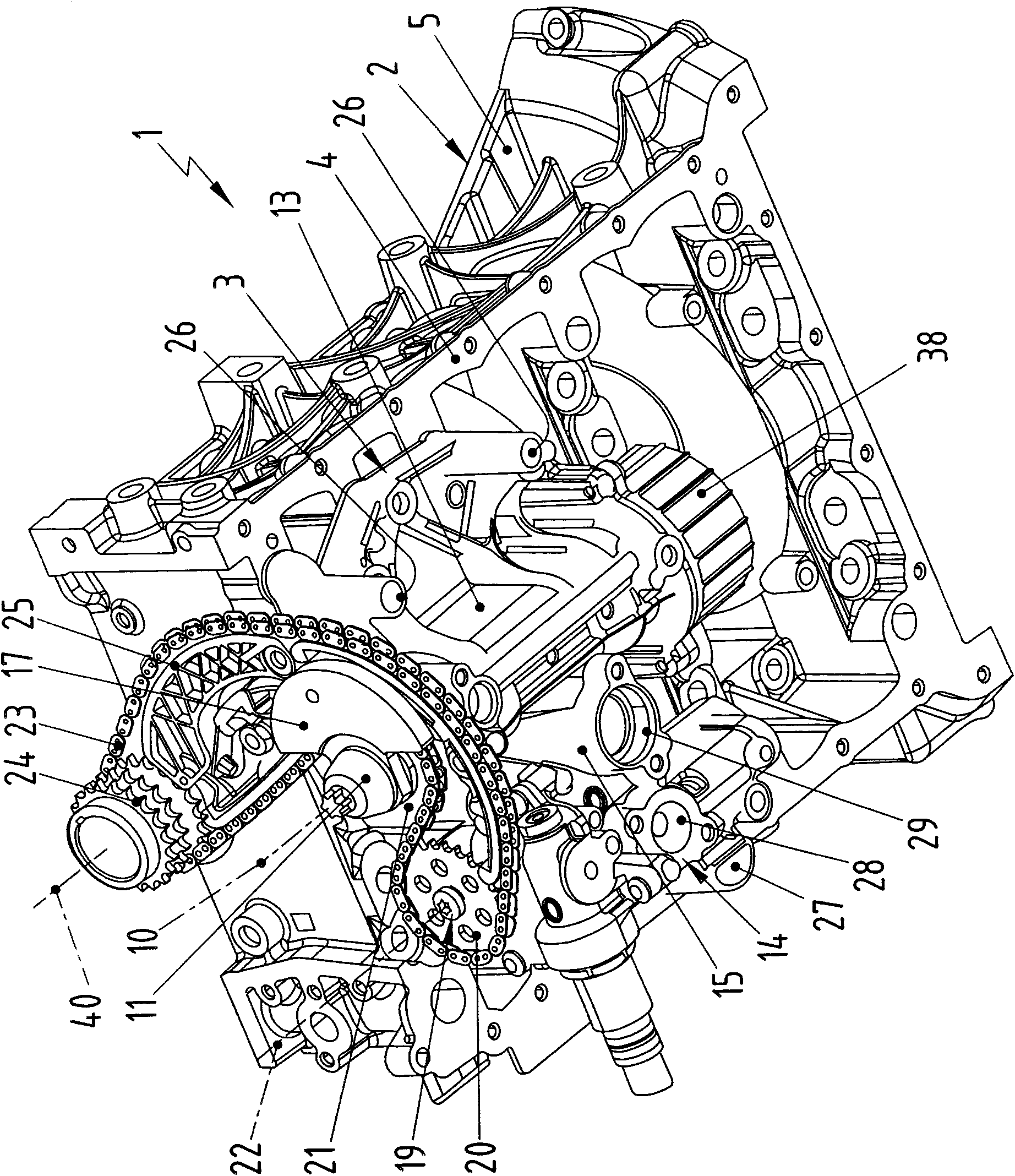
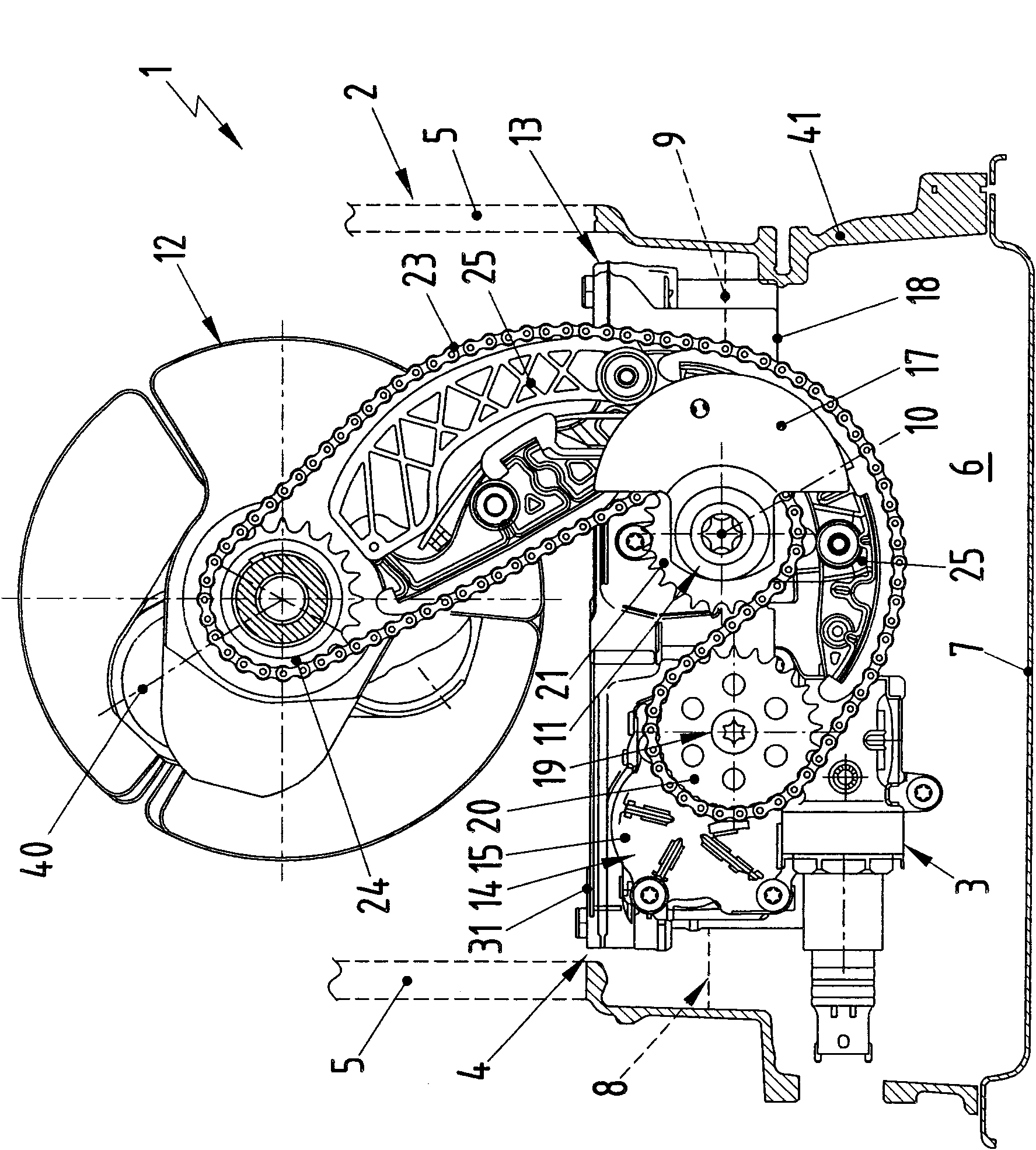
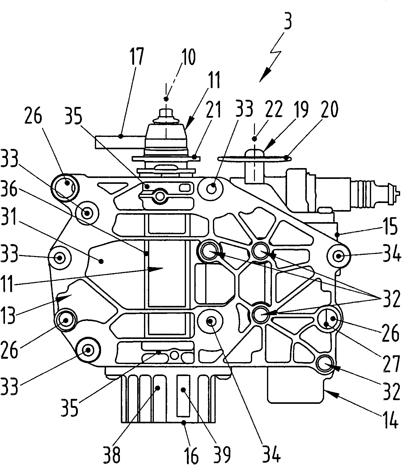
[0030] corresponds to figure 1 with figure 2 , a piston engine 1 , shown only in part, comprises a crankcase 2 and a balance shaft module 3 , which is mounted on or in the underside 4 of the crankcase 2 . In this context, the expressions "bottom" and "top" relate to the conventional installation situation of the piston engine 1 when it is used, for example, in a motor vehicle.

[0031] In crankcase 2, figure 1 with figure 2 Only one lower part 5 is shown, whose lower side 4 simultaneously forms the lower side 4 of the crankcase 2 . An oil guide housing 41 is mounted on the bottom of the crankcase 2 or on the bottom of the lower part 5 , which surrounds a cavity 6 laterally. In this way, the crankcase 2 has the cavity 6 together with the oil guide housing 41 on its underside 4 . The cavity 6 is open in the downward direction and closed in the downward direction by an oil pan 7 which is attached from below to the oil guide housing 41 of the crankcase 2 . The function of ...


PUM


Abstract

The invention relates to a balance shaft module used, specifically, for a piston engine of a motor vehicle. The balance shaft module has a balance shaft housing, which is provided with at least one balance shaft in a rotatable manner therein and is provided and installed on or in the middle of the lower side of a crankshaft box of the piston engine. In addition, the balance shaft module has an oil pump, the housing of which is fastened on the balance shaft housing. If the oil pump housing is arranged on the lower side of the balance shaft housing, then an especially compact design can be obtained.

Description

technical field [0001] The invention relates to a balance shaft module for a piston engine, in particular a motor vehicle, which has a balance shaft housing in which at least one balance shaft is rotatably mounted and which is provided for mounting in a On or in the underside of a crankcase of the piston engine there is an oil pump whose oil pump housing is fastened to the balance shaft housing. [0002] The invention also relates to a piston engine equipped with a balancing shaft module of the type described. Background technique [0003] US 5,535,643 discloses a balance shaft module comprising a balance shaft housing and an oil pump housing. In this known module, two balance shafts are rotatably mounted in a balance shaft housing. In this case, the balancing shaft housing is provided for mounting on the underside of a crankcase of the relevant piston engine. The oil pump housing contains an oil pump and is fastened to the balance shaft housing. In this known balancing ...

Claims


Application Information

Patent Timeline
Patent Type & Authority Applications(China)
IPC IPC(8): F16F15/26F02B67/04
CPCF01M2001/0276F01M1/02F02B67/06F16F15/267
Inventor C·阿佩尔D·伯恩哈特
Owner DR ING H C F PORSCHE AG
Learn More