Backlight module

A backlight module and light guide plate technology, applied in optics, light guides, light sources, etc., can solve problems such as troublesome assembly, long time, and inaccurate screw alignment, and achieve the effect of convenient assembly

Inactive Publication Date: 2010-12-22
AU OPTRONICS CORP
View PDF0 Cites 21 Cited by
  • Summary
  • Abstract
  • Description
  • Claims
  • Application Information

AI Technical Summary

Problems solved by technology

[0004] Based on the above, the conventional side-illuminated backlight module 100 needs to lock the frame 140 on the metal lampshade 110 by screws, so the assembly is more troublesome, and there will be problems with screw alignment, resulting in an increase in the defective rate
In addition, when rework (that is, reassembly) is required, it is necessary to take out the light guide plate 150 and loosen the screws first, so it will consume more time.

Method used


Image

  • Backlight module
  • Backlight module
  • Backlight module

Examples


Embodiment Construction

[0033] In order to further explain the technical means and effects of the present invention to achieve the intended purpose of the invention, the specific implementation, structure, characteristics and effects of the backlight module proposed according to the present invention will be described below in conjunction with the accompanying drawings and preferred embodiments. Details are as follows.

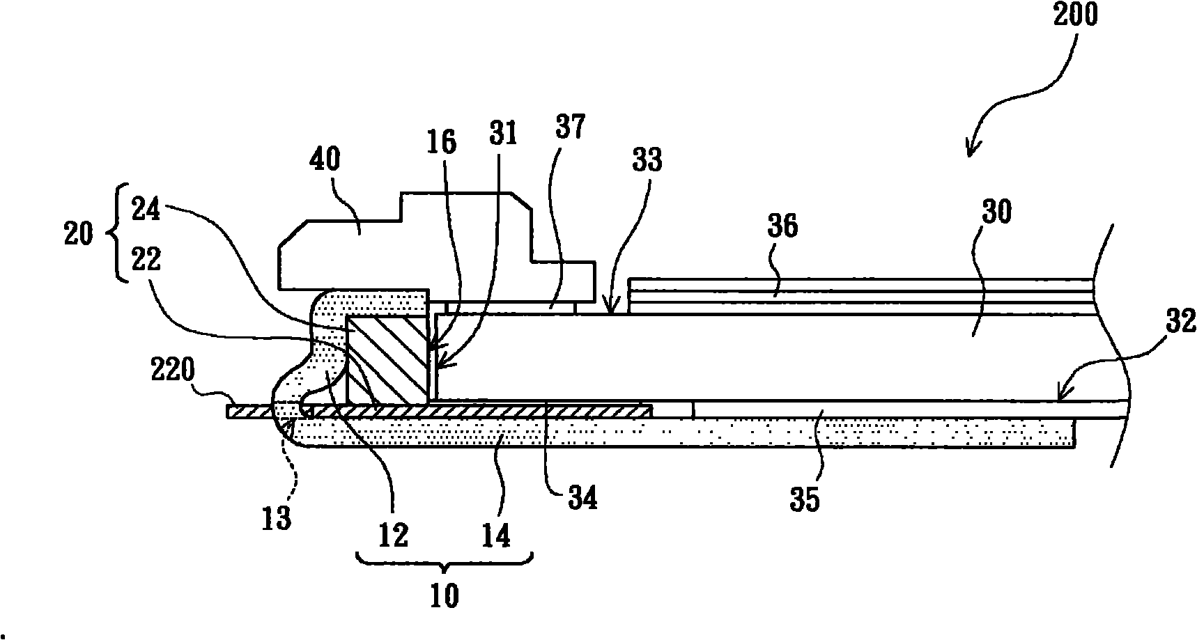
[0034] figure 2 It is a schematic diagram of a backlight module provided by an embodiment of the present invention. refer to figure 2 , The backlight module 200 provided by an embodiment of the present invention includes a reinforcing tape 10 , a light source assembly 20 and a light guide plate 30 .

[0035] The reinforcing tape 10 is bent to form a cover body 12 and a support portion 14 extending from the bottom of the cover body 12 , wherein the cover body 12 has an opening 16 . The light source assembly 20 is pasted on the cover body 12 and located inside the cover body 12 . ...


PUM


Abstract

The invention relates to a backlight module which comprises a strengthened adhesive tap, a light source assembly and a light guide plate. The strengthened adhesive tap is bent to form a shade, a supporting part extends out from the bottom of the shade, and the shade is provided with an opening; the light source assembly is attached to the shade and is arranged in the shade; and the light guide plate is provided with an incident surface, a bottom surface adjacent to the incident surface and an exit surface, a part of the bottom surface is opposite to the supporting part, and the incident surface is placed at the position of the opening. In the assembly of the backlight module, the backlight module can be directly attached to other members through the shade and can be assembled conveniently. In addition, when reworking is required, reworking can be carried out easily just by tearing off the strengthened adhesive tap without the locking of screws.

Description

technical field [0001] The invention relates to the field of liquid crystal displays, in particular to a backlight module for providing light sources for liquid crystal display panels. Background technique [0002] Since the liquid crystal display panel does not have self-luminous characteristics, in order to achieve the display effect, the backlight module needs to provide a display light source for the liquid crystal display panel. Backlight modules are divided into direct-lit backlight modules and side-illuminated backlight modules. figure 1 It is a schematic diagram of a known side-illuminated backlight module. see figure 1 , the conventional side-illuminated backlight module 100 includes a metal lampshade 110, a light emitting diode light source 120, a frame 140 for supporting a liquid crystal display panel, a light guide plate 150, a reflector 160 and a plurality of optical films 170 , wherein the LED light source 120 includes a printed circuit board 122 (printed ci...

Claims


Application Information

Patent Timeline
Patent Type & Authority Applications(China)
IPC IPC(8): F21S8/00F21V3/02F21V3/04F21V19/00F21V8/00F21V17/10G02F1/13357F21Y101/02
Inventor 许文铭黄冠富谢敏生
Owner AU OPTRONICS CORP
Why Eureka
Try Eureka