Thermal circulation type elevated heatable brick bed

An overhead kang and thermal cycle technology, which is applied in heating methods, furnace combustion air/flue gas circulation, household heating, etc., can solve problems such as poor convective heat transfer, and achieve improved thermal efficiency, simple structure, and energy saving Effect

Inactive Publication Date: 2012-05-23
HARBIN INST OF TECH
View PDF0 Cites 0 Cited by
  • Summary
  • Abstract
  • Description
  • Claims
  • Application Information

AI Technical Summary

Problems solved by technology

[0003] The purpose of the present invention is to provide a heat circulation type overhead kang, which is used for the problem that the existing overhead kang has a heat stagnation area and indoor convective heat transfer is not good

Method used


Image

  • Thermal circulation type elevated heatable brick bed
  • Thermal circulation type elevated heatable brick bed
  • Thermal circulation type elevated heatable brick bed

Examples


Embodiment 1

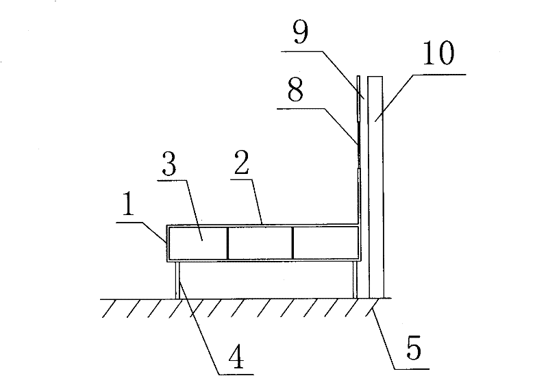
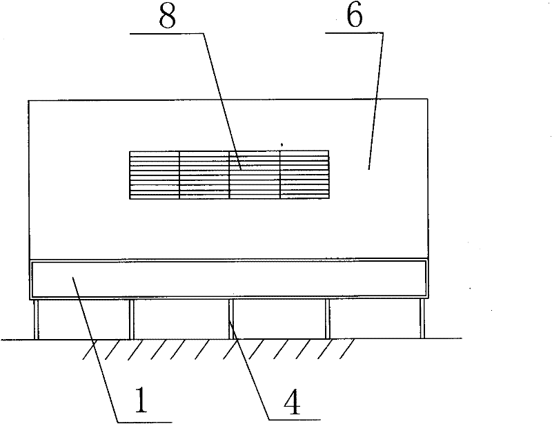
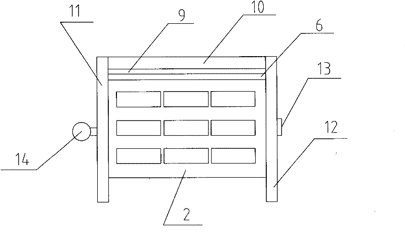
[0018] combine figure 1 , figure 2 , image 3 As shown, there is a flue 3 in the body 1 of the thermal cycle overhead kang, and the body 1 contacts the ground 5 through the support column 4, and the support column 4 supports the body 1 away from the ground 5, so that the bottom surface of the body 1 An air channel is formed between the ground 5, the left and right sides of the kang body 1 are respectively built with the left side wall 11 and the right side wall 12, and the back of the kang body 1 is a heat dissipation wall 6, and the heat dissipation wall 6 stands on the kang surface 2, Behind the cooling wall 6 is the back wall 10 of the room, the cooling wall 6 is separated from the back wall 10, the space between the two is the air flow channel 9, the top of the air flow channel 9 is the outlet of the circulation port, the air channel and the The air flow passage 9 is connected, and the two form a right-angle passage. The heat dissipation wall 6 is made of heat dissipat...

Embodiment 2

[0020] Figure 4 It is a side sectional view of Embodiment 2 of the present invention. As shown in the figure, the difference between this heat-circulating overhead kang and the thermal-circulation overhead kang in Embodiment 1 is that there is a row of support columns 4 on the front of the kang body 1, and the kang body There is also a row of supporting columns 4 behind the 1, wherein the supporting columns 4 at the back directly lean against the back wall 10 of the room, and the kang body 1 is seated on the supporting columns 4, and the upper end surface of the supporting columns 4 is partially exposed outside the kang body 1. This way is more stable because the support column 4 at the back leans against the back wall 10 , and the part of the support column 4 exposed outside the kang body 1 is formed as the air flow channel 9 between the heat dissipation wall 6 and the back wall 10 .

[0021] The present invention designs the structure of heated kang according to the princip...


PUM


Abstract

The invention relates to a thermal circulation type elevated heatable brick bed, which belongs to a novel heated brick bed used in houses of villages and small towns. A flue is nailed in the heatable brick bed body of the thermal circulation type elevated heatable brick bed, wherein the heatable brick bed body is contacted with the ground through supporting columns; an air passage is formed between the bottom surface of the heatable brick bed body and the ground; a heat dissipation wall which stands on a heatable brick bed plane is arranged behind the heatable brick bed body; the rear wall ofa room is arranged behind the heat dissipation wall; an air flow passage is formed between the heat dissipation wall and the rear wall; and the air passage is communicated with the air flow passage. The air passage below the heatable brick bed body and the air flow passage between the heat dissipation wall and the rear wall form an air circulating passage so as to have the effect of a chimney; and thus the elevated heatable brick bed solves the problem of heat retention existing in the conventional elevated heatable brick bed well, makes the indoor air truly flow and improves the heat efficiency of the heated brick bed.

Description

1. Technical field: [0001] The invention relates to a novel heated kang used in houses in villages and towns, in particular to a thermal cycle overhead kang. 2. Background technology: [0002] At present, the heated kang is still very common in vast rural areas. The heated kang is connected to the stove and is arranged in two rooms respectively. The heated kang is heated by burning the stove. The heated kang is made of materials such as brick and soil. Bricks, cement boards, etc. The overhead kang is a kind of heated kang. The overhead kang is directly built on the ground with adobe, bricks, cement boards, etc. The three sides of the kang body are directly connected with the two walls and the back wall of the room. There is a heat stagnation area on the lower bottom of the kang, the circulation is not smooth, the indoor air temperature exchange rate is slow, and the thermal efficiency is low, resulting in uneven indoor heat. 3. Contents of the invention: [0003] The obje...

Claims


Application Information

Patent Timeline
Patent Type & Authority Patents(China)
IPC IPC(8): F24B5/02E04F17/02
Inventor 李桂文任洪国方修睦
Owner HARBIN INST OF TECH
Why Eureka
Try Eureka