
Electrical connector having improved electrical characteristics

一种电连接器、连接器的技术,应用在电端子领域,能够解决忽视电端子安装端、没有修改电端子等问题

Inactive Publication Date: 2010-12-22
TE CONNECTIVITY CORP
View PDF5 Cites 12 Cited by
  • Summary
  • Abstract
  • Description
  • Claims
  • Application Information

AI Technical Summary

Problems solved by technology

[0004] Previous attempts to design such high-speed electrical connectors have focused on the mating ends of the electrical terminals in the connector to achieve desired levels of impedance and crosstalk, pin density, and other desired electrical and mechanical characteristics, but these attempts have largely on the mounting end that has overlooked the electrical terminals within the connector
For example, previous attempts to reduce crosstalk within a connector and obtain desired impedance levels associated with side-coupling or side-to-side positioning using mating ends of electrical terminals within a connector did not include any suggestion to modify the mounting ends of electrical terminals, and these recommendations will have any desired mechanical or electrical effect within the connector

Method used


Image

  • Electrical connector having improved electrical characteristics
  • Electrical connector having improved electrical characteristics
  • Electrical connector having improved electrical characteristics

Examples


Embodiment Construction

[0025] Wherever possible, the same reference numbers will be used throughout the drawings to refer to the same or like parts.

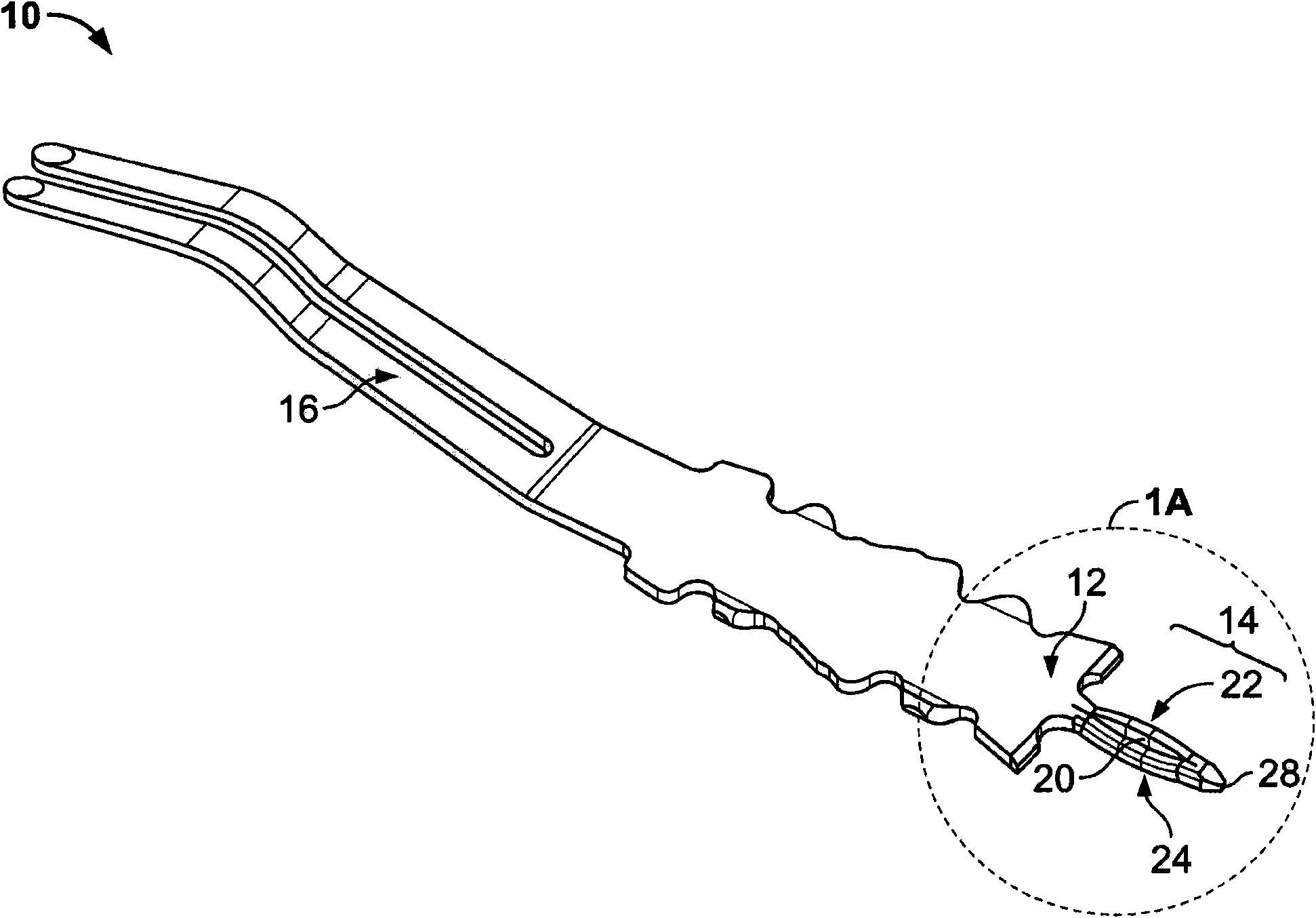
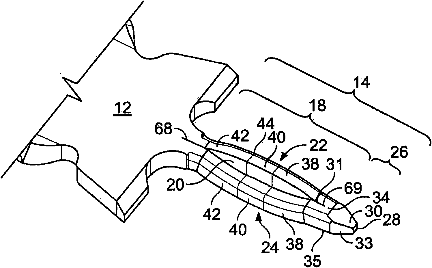
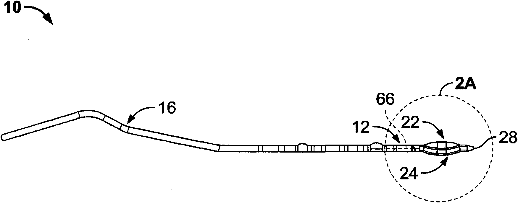
[0026] Various embodiments of the present invention include, for example, electrical terminals and electrical connectors having desired electrical and mechanical characteristics, such as desired impedance levels, impedance distribution, insertion loss, crosstalk levels, pin density, and / or insertion force distribution. In some embodiments, these desirable characteristics are achieved by electrical terminals having mounting ends that are substantially smaller than their mating ends. In other embodiments, an electrical connector, such as a press-fit connector, has a plurality of electrical terminals with mounting ends configured to provide improved characteristics. These and other embodiments are described in more detail below.

[0027] One embodiment of the invention is directed to electrical terminals 10, also known as contacts or prongs, such as F...


PUM


Abstract

An electrical connector (70) for mounting on a substrate comprises a housing (76) and a plurality of signal contacts (10) positioned in the housing. Each of the contacts defines a mating end (16) and a mounting end (14). The mating end and the mounting end each define a width. The mounting end comprises a compliant pin section and defines a width that is less than about 60% of the width of the mating end. The connector has a contact density of at least about 90 contacts per square inch. The connector has a worst case multi-aggressor asynchronous differential cross-talk of less than about three percent at an initial rise time of approximately 40 picoseconds.

Description

[0001] This application is a continuation-in-part of US Application Serial No. 11 / 462,012, filed August 2,2006. technical field [0002] The present invention relates to an electrical terminal of the type inserted into an aperture of a switchboard member and an electrical connector including the same. Background technique [0003] As the complexity of electronic components increases, it is desirable to fit more components into a smaller space on a circuit board or other substrate. Accordingly, the spacing between electrical terminals within the connector has been reduced, while the number of electrical terminals accommodated in the connector has increased, thereby increasing the need for such electrical connectors in electrical technology, the electrical connection Processors can process at ever higher speeds and can be implemented with ever greater pin densities. It is desirable that these connectors not only have fairly constant impedance levels, but also have acceptable ...

Claims


Application Information

Patent Timeline
Patent Type & Authority Applications(China)
IPC IPC(8): H01R12/32H01R24/00H01R12/55
CPCH01R12/52H01R12/724H01R23/688H01R23/005H01R12/585H01R13/6587H01R13/6477H01R13/514H01R12/7064H01R23/7073H01R13/6471
Inventor 詹姆斯·L·费德道格拉斯·W·格洛弗戴维·W·赫尔斯特查德·W·摩根布伦特·R·罗瑟梅尔亚历克斯·M·沙夫阿塔利·S·泰勒戴维·A·特劳特
Owner TE CONNECTIVITY CORP
Learn More