Method and apparatus for optimally laser marking articles

a laser marking and laser technology, applied in metal working apparatus, manufacturing tools, thermography, etc., can solve the problems of uneven and commercially unacceptable, unacceptably low throughput, and different thresholds, and achieve the effect of desirable appearan

Inactive Publication Date: 2012-02-23
ELECTRO SCI IND INC
View PDF10 Cites 39 Cited by
  • Summary
  • Abstract
  • Description
  • Claims
  • Application Information

AI Technical Summary

Benefits of technology

[0014]Another aspect of this invention relies upon an infrared (IR) camera focused on the article to measure the temperature of the article as it is being marked. The infrared camera detects the heat emitted from the surface of the article in an area to be marked and communicates this information to the controller which adjusts the laser fluence to co

Problems solved by technology

The difficulty is that these thresholds can be different for different areas of the mark at different times during the marking process.
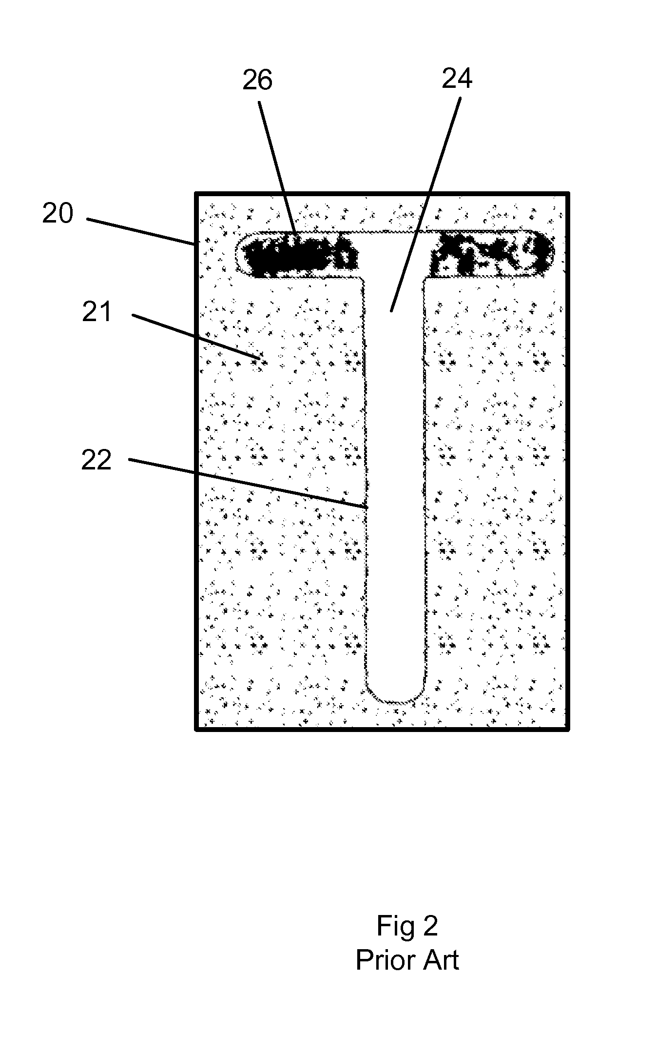
Laser parameters which provide commercially desirable appearance and acceptable rate of material removal and hence throughput in one area of the mark may damage the underlying material in another area of the mark. FIG. 2 shows the results of laser marking an article with a single irradiance and rate of travel, wherein the results are uneven and commercially unacceptable.
Ch

Method used


Image

  • Method and apparatus for optimally laser marking articles
  • Method and apparatus for optimally laser marking articles
  • Method and apparatus for optimally laser marking articles

Examples


Embodiment Construction

[0023]An embodiment of this invention creates a mark with desired properties on coated articles using a laser marking system. The laser marking system has data storage and controllable laser fluence or dose. Embodiments of this invention determine a first laser fluence associated with creating a mark with desired properties on a first portion of the mark. Aspects of this invention then determine a second laser fluence associated with creating a mark with desired properties on a second portion of the mark. These fluences are then stored in the laser marking system's storage. The laser marking system is then directed to mark the article using the stored first laser fluence in the first portion of the mark and using the stored second laser fluence in a second portion of the mark thereby marking the article with desired properties. Embodiments of this invention control laser fluence by controlling various laser parameters including laser pulse parameters such as pulse duration or pulse ...


PUM

PropertyMeasurementUnit
Surface energyaaaaaaaaaa
Temperatureaaaaaaaaaa

Abstract

The invention is a method and apparatus for laser marking a stainless steel specimen with commercially desirable marks. The method includes providing a laser processing system having a laser, laser optics and a controller with pre-determined laser pulse parameters, selecting the pre-determined laser pulse parameters associated with the desired mark, and directing the laser marking system to produce laser pulses having laser pulse parameters associated with the desired marks including temporal pulse widths greater than about 1 and less than about 1000 picoseconds.

Description

TECHNICAL FIELD[0001]The present invention relates to laser marking articles. In particular it relates to laser marking articles by laser ablating a coating applied to the article which reveals the surface of the article underneath, thereby forming the mark by the contrasting appearance between the revealed surface of the article and the adjacent remaining coating. The mark may also be formed by laser ablating the first or topmost coating layer to reveal a second coating layer underneath forming the mark by the contrast between the revealed second coating and adjacent first coating. Laser parameters are selected to provide uniform, commercially desirable appearance and avoid damage to the underlying surface while maintaining acceptable system throughput.BACKGROUND OF THE INVENTION[0002]Marketed products commonly require some type of marking on the product for commercial, regulatory, cosmetic or functional purposes. A mark is defined as contiguous region or area on the surface of the...

Claims


Application Information

Patent Timeline
IPC IPC(8): B23K26/38B23K26/06B23K26/40
CPCB23K26/4095B23K26/40B41M5/26B23K2101/35
Inventor HOWERTON, JEFFREYREICHENBACH, ROBERTALPAY, MEHMET
Owner ELECTRO SCI IND INC
Why Eureka
Try Eureka