Carrier phase detection system for radar sensors

a carrier phase detection and radar sensor technology, applied in the direction of distance measurement, amplitude demodulation, pulse technique, etc., can solve the problems of detectors having difficulty detecting a particular sinewave cycle, detecting pulsed rf, and approaching unattractive, so as to achieve high dynamic range, high accuracy, and high accuracy

Active Publication Date: 2008-05-27
MCEWAN TECH
View PDF15 Cites 36 Cited by
  • Summary
  • Abstract
  • Description
  • Claims
  • Application Information

AI Technical Summary

Benefits of technology

[0016]The present invention can be used in expanded time radar, laser, and TDR ranging systems as a high accuracy detection system that exhibits high accuracy, high dynamic range and excellent immunity to noise. Applications include pulse echo rangefinders for tank level measurement, environmental monitoring, industrial and robotic controls, digital handwriting capture, imaging radars, vehicle backup and collision warning radars, and universal object / obstacle detection and ranging.
[0017]One object of the present invention is to provide a precision pulsed RF radar pulse detection system. A further object is to provide a precision pulsed RF radar pulse detection system with high immunity to noise, interference and baseline clutter. Another object of the present invention is to provide a precision pulse detection system for TDR systems employing pulsed RF bursts.

Problems solved by technology

A problem arises in precisely detecting pulsed RF produced by these systems.
One sinewave cycle looks very much like the next within a sinewave burst, so a detector has difficulty detecting a particular sinewave cycle within the burst.
Unfortunately, variations in received signal amplitude make this approach unattractive since cycle jumps are inevitable as amplitude varies with target range, aspect angle and size.
In all these cases, the envelope is slower and of lower bandwidth than an individual cycle within the burst, and so detection accuracy suffers accordingly.
A ten fold reduction in accuracy is not uncommon with these envelope detection techniques.
This approach, while effective, has two limitations.
However, the '990 patent fails to teach detection of multiple sinusoids in a burst—it is limited to single transients.
Multiple cycles within a burst present an ambiguity as to which cycle to detect, and this problem is not addressed in the '990 patent.
Furthermore, the '990 patent is limited to an analysis window derived from a single transient above threshold.

Method used


Image

  • Carrier phase detection system for radar sensors
  • Carrier phase detection system for radar sensors
  • Carrier phase detection system for radar sensors

Examples


Embodiment Construction

[0025]A detailed description of the present invention is provided below with reference to the figures. While illustrative component values and circuit parameters are given, other embodiments can be constructed with other component values and circuit parameters. All U.S. patents and copending U.S. applications cited herein are herein incorporated by reference.

General Description

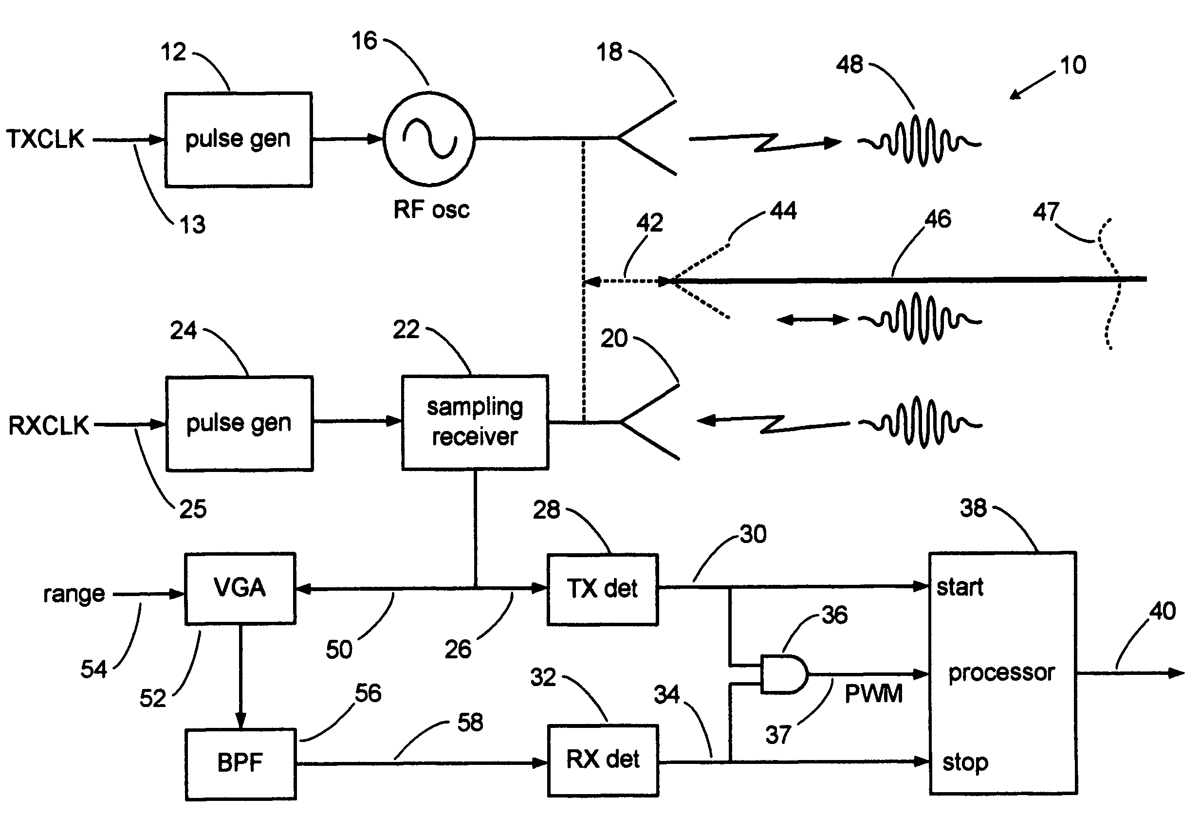
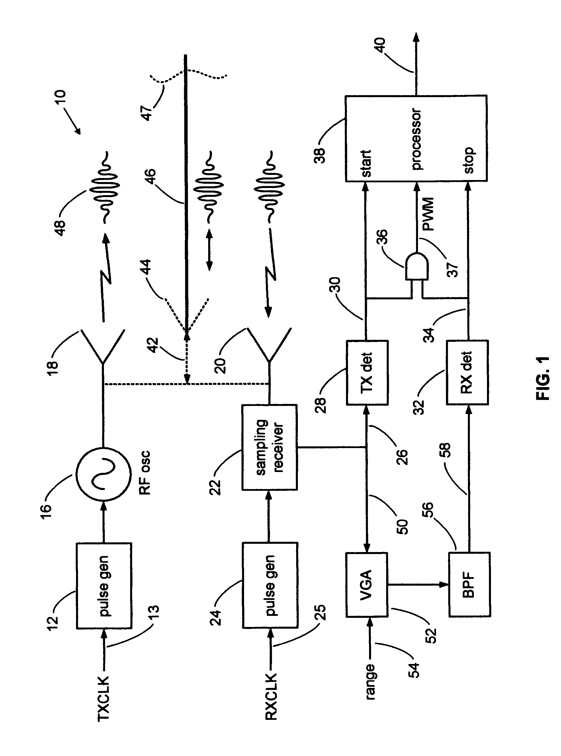
[0026]The present invention overcomes the limitations of the various prior detection techniques by detecting the time-of-peak (TOP) of the expanded time RF burst envelope within an analysis window of time and then using that detection event to gate a carrier phase detector. The carrier phase detector detects the zero axis crossings of each sinewave cycle within a burst. The zero axis crossing of a selected cycle is gated by the TOP detection. Therefore, the accuracy of the detection is directly tied to the selected sinewave zero axis crossing, which is highly accuracy, and not to the TOP accuracy. Furthermore,...


PUM


Abstract

A pulse detection system for expanded time radar, laser and TDR sensors detects specific cycles within bursts of cycles. A sensor transmits and receives short bursts of RF cycles. A transmit pulse detector triggers on a selected cycle of the detected transmit burst and starts a range counter. A receive detector triggers on a selected cycle within a received echo burst to stop the range counter, thereby indicating range. Cycle selection is enabled by an analysis window of time. The detection system can provide accuracies on the order of one picosecond and is well-suited to accurate ranging along an electromagnetic guide wire.

Description

BACKGROUND OF THE INVENTION[0001]1. Field of the Invention[0002]The present invention relates to radar detection circuits and more particularly to baseband carrier detection circuits for expanded time ranging systems. The invention can be used to accurately detect the time of occurrence of pulsed RF echoes for sampling radar, TDR (Time Domain Reflectometry) and laser sensors.[0003]2. Description of Related Art[0004]Short range, high resolution pulse-echo ranging systems, such as wideband and ultra-wideband pulsed radar and pulsed laser rangefinders often transmit a short sinusoidal burst on the order of 1-nanosecond in duration and consisting of about six cycles of RF. Radars having these parameters can be found in, for example, commercial pulse-echo rangefinders used to determine liquid levels in tanks. These radars operate in an expanded time mode, whereby the transmit pulse rate is slightly higher than the receiver gate, or sampling, rate, to produce a stroboscopic slow motion sa...

Claims


Application Information

Patent Timeline
Patent Type & Authority Patents(United States)
IPC IPC(8): G01S7/00G01S17/02G01S7/02G01S7/48G01S13/00G01S17/00G01S7/4865G01S17/14
CPCG01S7/285G01S7/484G01S13/106G01S13/16G01S13/30G01S17/105G01S7/4865G01S7/4873G01S17/14
Inventor MCEWAN, THOMAS EDWARD
Owner MCEWAN TECH
Why Eureka
Try Eureka