Vehicle floor cloth laying device
A floor and pavement technology, which is applied in the field of vehicle floor cloth paving devices, can solve the problems of low work efficiency, high labor intensity of workers, time-consuming and labor-intensive operation of workers, etc., and achieve the goal of improving work efficiency, reducing labor intensity, and simple operation Effect
- Summary
- Abstract
- Description
- Claims
- Application Information
AI Technical Summary
Problems solved by technology
Method used
Image
Examples
Embodiment 1
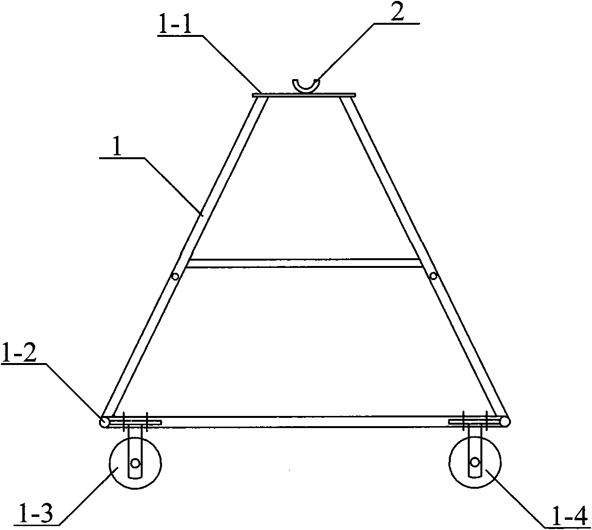
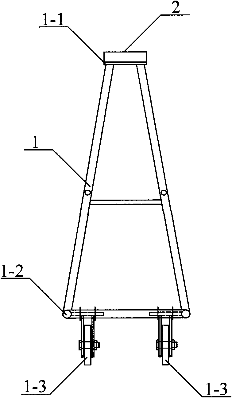
[0027] refer to figure 1 and figure 2 , shows a schematic structural view of Embodiment 1 of the vehicle floor cloth laying device, wherein, figure 1 It is the front view of Embodiment 1 of the vehicle floor cloth laying device; figure 2 It is a side view of Embodiment 1 of the vehicle floor cloth laying device. The vehicle floor cloth laying device comprises: a fixed bracket 1, and a concave support part 2 supporting a floor cloth roll. The concave supporting part 2 is arranged on the top 1 - 1 of the fixed bracket 1 .
[0028] In this embodiment, the concave supporting part 2 can be but not limited to be fixedly connected to the top 1-1 of the fixing bracket by welding. The fixed support 1 may be a trapezoidal support comprising: a top 1-1 and a bottom 1-2, and the middle is supported by four longitudinal beams. In order to facilitate the movement of the floor cloth laying device and the overall movement after carrying the weight of the floor cloth, four pulleys are i...
Embodiment 2
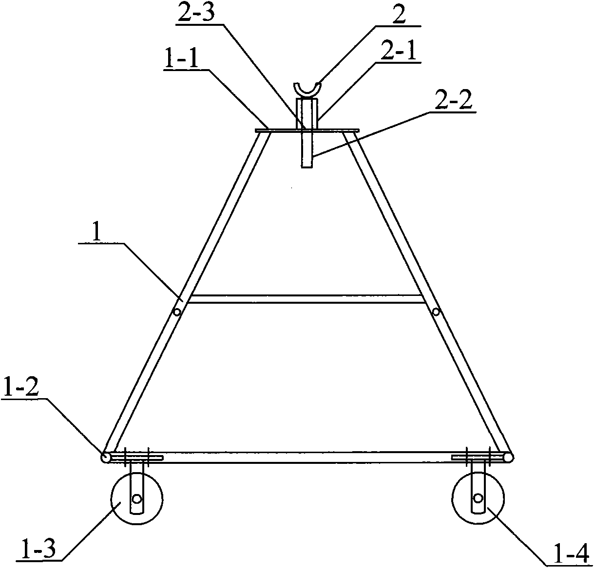
[0037] refer to image 3 and Figure 4 , shows a schematic structural diagram of Embodiment 2 of the vehicle floor cloth laying device, wherein, image 3 It is the front view of Embodiment 2 of the vehicle floor cloth paving device; Figure 4 It is a side view of the second embodiment of the vehicle floor cloth laying device. The vehicle floor cloth laying device comprises: a fixed bracket 1, and a concave support part 2 supporting a floor cloth roll.
[0038] The difference between this embodiment and the first embodiment is that the arrangement of the concave support part 2 on the top 1 - 1 of the fixing bracket 1 is different. In this embodiment, a rotating bracket 2-1 is fixedly connected to the top 1-1 of the fixed bracket 1 . Correspondingly, the bottom of the concave support part 2 is fixedly connected with a rotating shaft 2-2. The rotating shaft 2-2 can be inserted in the rotating bracket 2-1, and rotates freely in the bracket.
[0039] As a preferred embodiment...
PUM
 Abstract
Description
Claims
Application Information
 - R&D
- Intellectual Property
- Life Sciences
- Materials
- Tech Scout
- Unparalleled Data Quality
- Higher Quality Content
- 60% Fewer Hallucinations
Browse by: Latest US Patents, China's latest patents, Technical Efficacy Thesaurus, Application Domain, Technology Topic, Popular Technical Reports.
© 2025 PatSnap. All rights reserved.Legal|Privacy policy|Modern Slavery Act Transparency Statement|Sitemap|About US| Contact US: help@patsnap.com


