Excavator boom

A technology for excavators and sticks, applied in the field of excavator sticks, can solve problems such as troublesome installation of pipelines, and achieve the effects of reducing weight and avoiding the danger of cracking

Inactive Publication Date: 2010-12-29
LEIBHERR HYDRAULIKBAGGER GMBH
View PDF3 Cites 6 Cited by
  • Summary
  • Abstract
  • Description
  • Claims
  • Application Information

AI Technical Summary

Problems solved by technology

Although it is advantageous from the point of view of protecting the pipelines to arrange the pipelines in the arm of the exca

Method used


Image

  • Excavator boom
  • Excavator boom
  • Excavator boom

Examples


Embodiment Construction

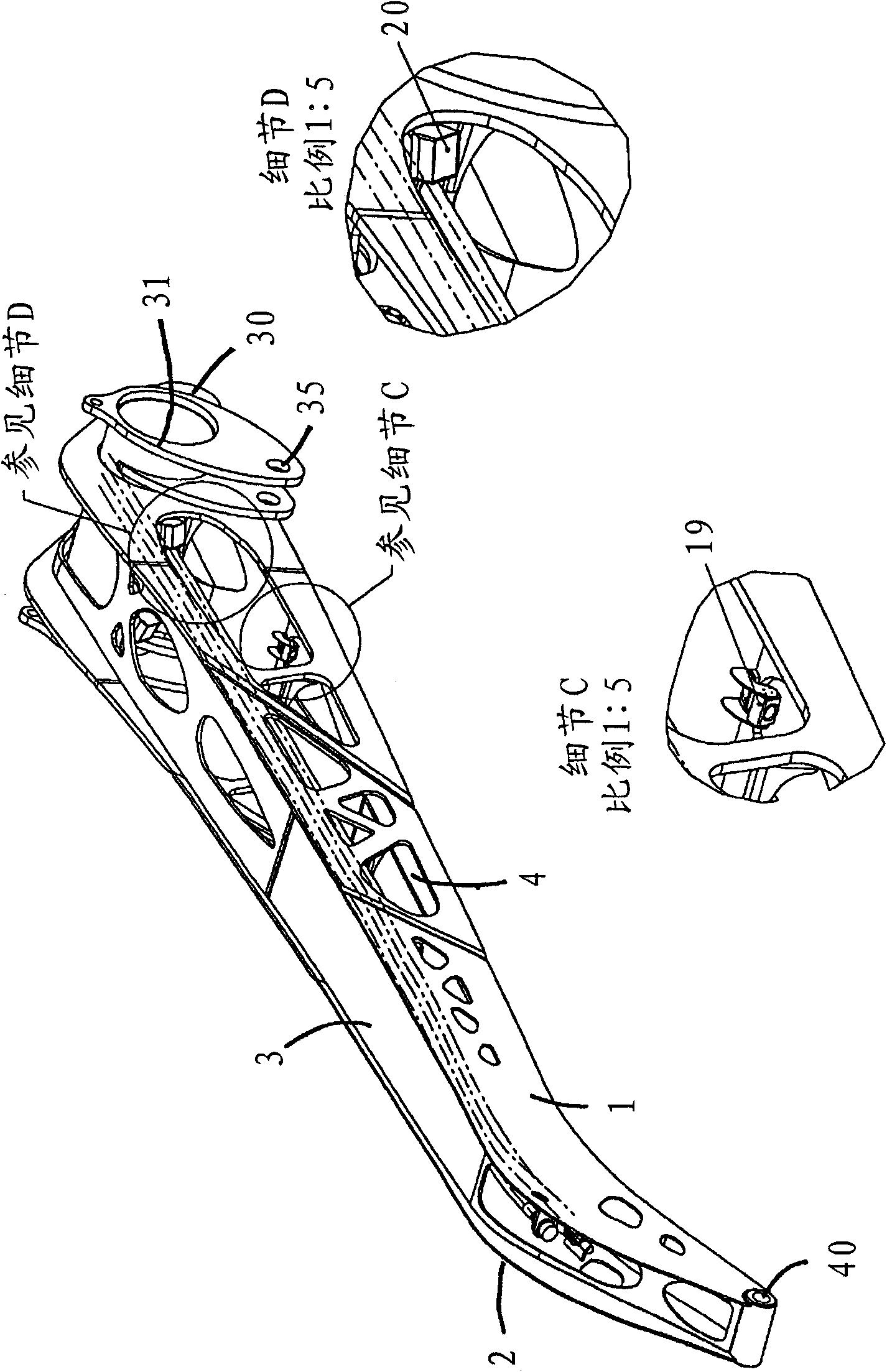
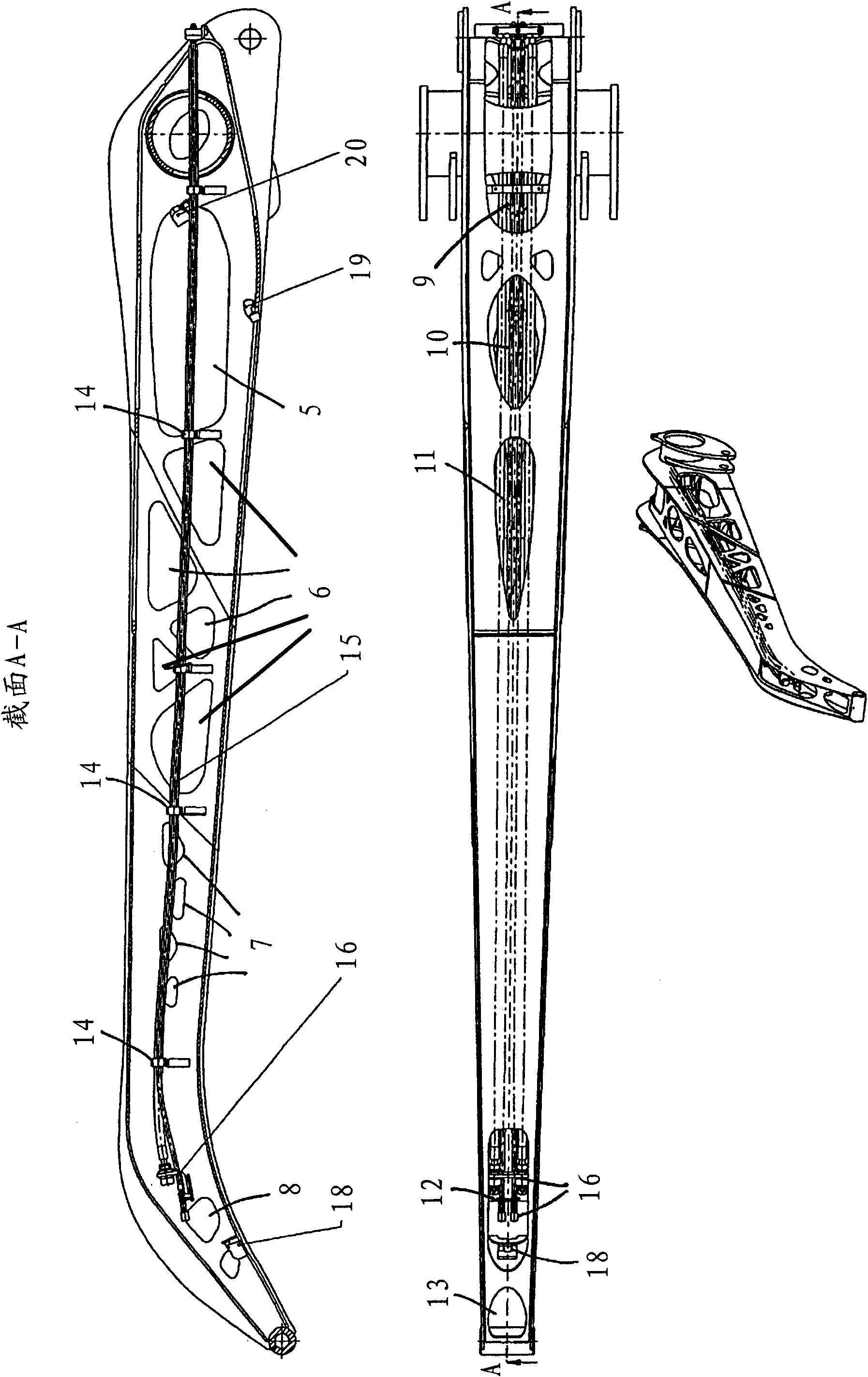
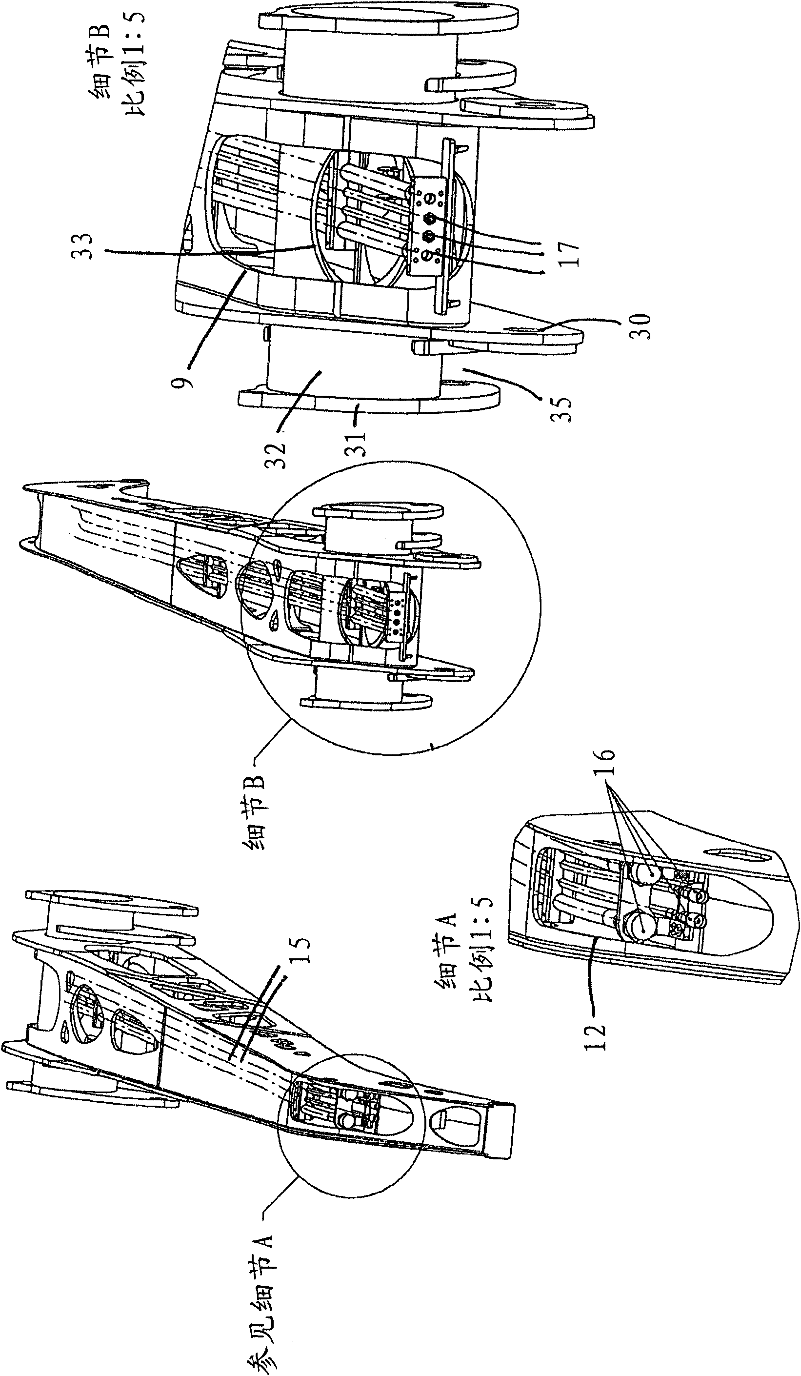
[0035] in Figure 1 to Figure 3 Shows an embodiment of an excavator stick according to the present invention. Here, the excavator arm has a box beam composed of a top plate 3, a bottom plate 4, and a first side plate 1 and a second side plate 2. The plates are welded to each other here to form a welded structure. According to the present invention, the inside of the box beam can now be accessed through a plurality of notches 5-13, which are arranged in the side plates 1, 2 and the top and bottom plates 3, 4 along the longitudinal direction of the excavator arm. In this regard, especially from figure 2 See this arrangement and structure of the notch.

[0036] The side plates 1 and 2 first have a large opening in the vicinity of the hinge area where the excavator arm has a large cross section. This is followed by an area with a number of larger openings 6 which are opened in the side panels along the narrowing of the excavator arm. These openings 6 are here essentially triangu...


PUM


Abstract

This invention relates to a box section made of an upper and lower plate and side plates. The upper and lower plates and the side plates thus form a weldment. According to the invention, provision is made for the interior of the box section to be accessible from the outside through multiple cutouts that are arranged in the longitudinal direction of the excavator boom in the side plates and/or in the upper and/or lower plates.

Description

Technical field [0001] The present invention relates to an excavator arm having a box beam composed of a top plate, a bottom plate and two side plates. The top plate, bottom plate and two side plates constitute a welding structure here. Background technique [0002] In the known excavator arm, the top plate, the bottom plate and the two side plates constitute a closed box beam, wherein the hydraulic line extends along the top plate, for example, on the outside. In addition, a part of such box girder is also known in which hydraulic lines extend inside the box girder. For this reason, sometimes a maintenance port is provided in the box beam so as to be able to connect to the power supply pipeline in the box beam. [0003] German Patent Publication No. DE19958696C2 discloses an excavator stick according to a box-shaped longitudinal frame structure. It includes a top plate, a bottom plate and two side plates. Along the frame structure, it is used for pressure medium, current, etc. ...

Claims


Application Information

Patent Timeline
IPC IPC(8): E02F3/38
CPCE02F9/2275E02F3/38
Inventor D·阿萨姆T·齐特尔巴特
Owner LEIBHERR HYDRAULIKBAGGER GMBH
Why Eureka
Try Eureka