Lock

A lock head and lock cylinder technology, which is applied to building locks, lock shells, cylinder pin locks, etc., can solve problems such as cramped layout of parts, damage to the overall strength of the lock cylinder, and unfavorable service life of the lock head, so as to improve the overall strength , the effect of improving reliability

Active Publication Date: 2010-12-29
马学文
View PDF2 Cites 0 Cited by
  • Summary
  • Abstract
  • Description
  • Claims
  • Application Information

AI Technical Summary

Problems solved by technology

The disadvantage is that the steel ball and code identification piece can only move radially in the lock cylinder. Considering the force of the code identification piece, the steel ball has to be set in the marble area, which makes the layout of the parts extremely cramped.
The deficiency of idling lock is: at first, the task of pushing the identification chip (idling lock is called auxiliary marble) away from the password gap (idling lock is called V-shaped ring groove, V-shaped notch) is to rely on the password on the inner slingshot. The notch is completed using the principle of a slope
This will also affect the reliability of the lock
In addition, in order to accommodate the code identification chip, this patent also has an open through long slot on one or both sides of the lock cylinder, resulting in damage to the overall strength of the lock cylinder
[0006] The difference between the code identification chips of the above two patents is that the code identification and return of the code identification chips of the atomic lock move radially, and the code identification chips are operated by the return position except when the lock is unlocked. The spring directly pushes away from the inner pin, so that the return spring away from the inner pin is in a relatively relaxed state most of the time; Except for the time, the rest of the time is pressed on the inner pin. The spring that presses the code disc to the inner pin is in a compressed state most of the time, and the spring is in a compressed state most of the time. For the service life of the lock head is unfavorable

Method used


Image

  • Lock
  • Lock
  • Lock

Examples


Embodiment 1

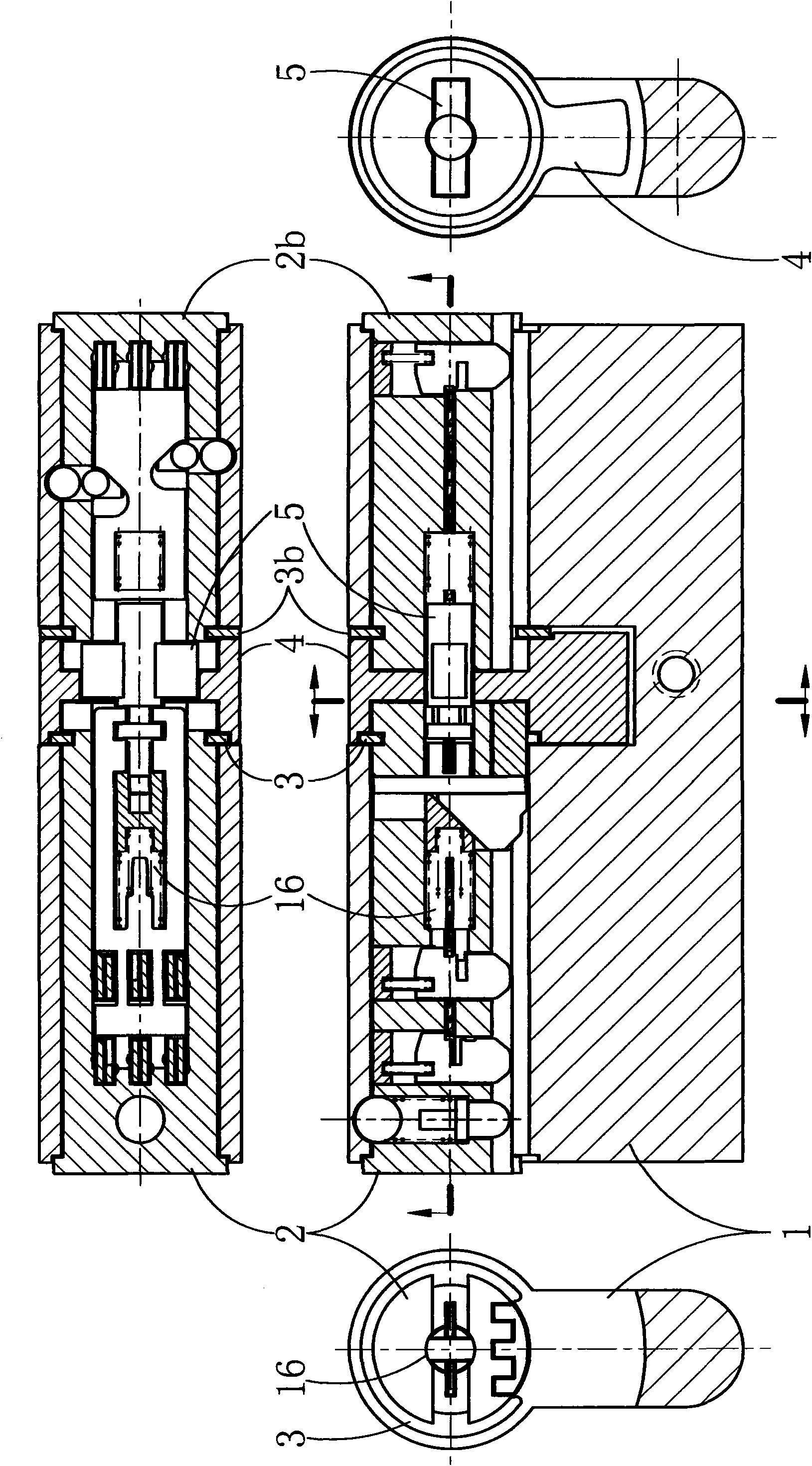
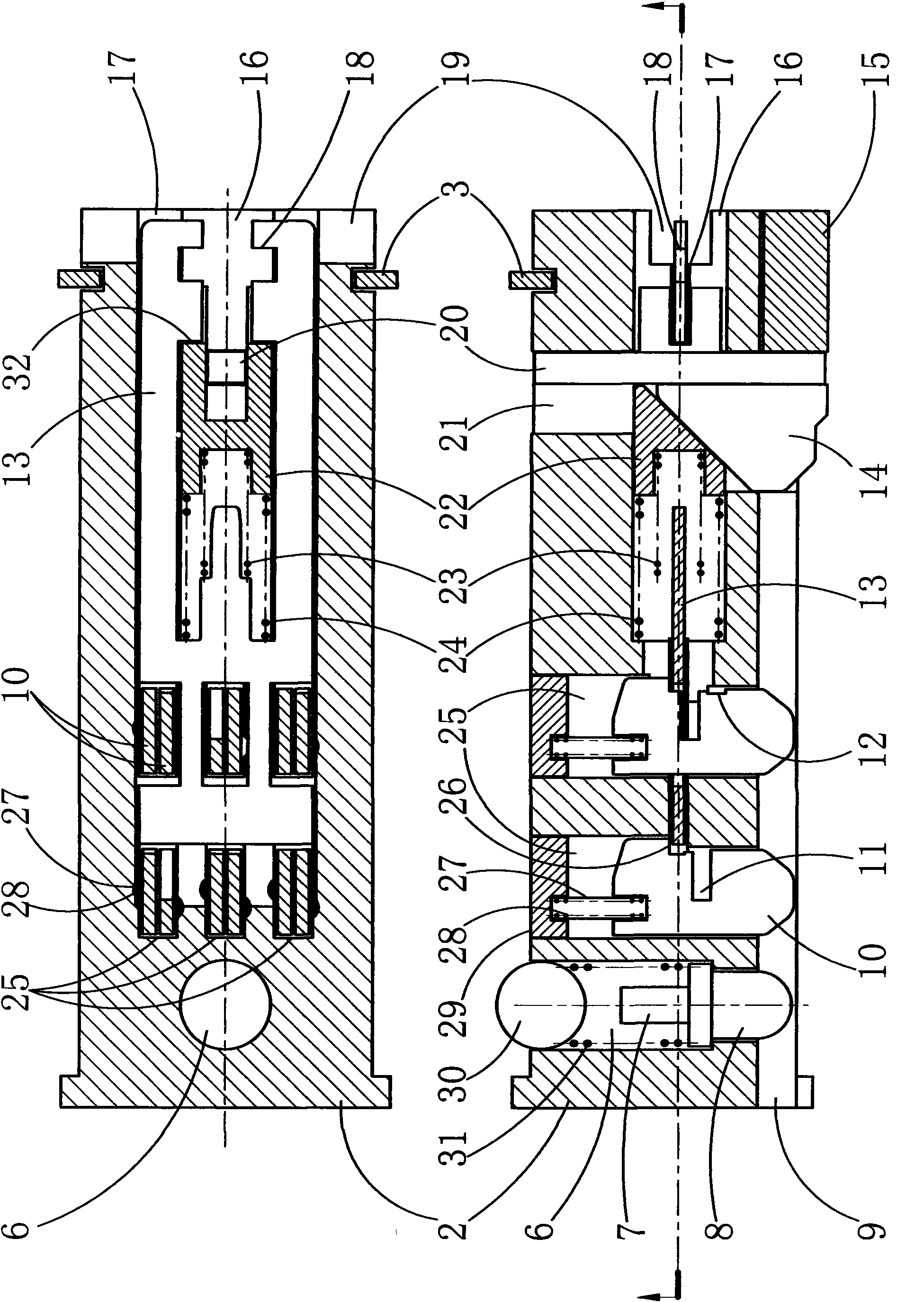
[0030]The outer door lock cylinder in this embodiment adopts an axial normally open code disc, a key drive device including a wire tooth key, and a pull-on clutch bolt, and is equipped with an anti-misoperation device; the door inner lock in this embodiment The lock cylinder adopts an axially normally open code discriminator and a beaded lock cylinder pin (the beaded lock core pin is also used as a driving device—a twisting drive device for an axially normally open code discriminator); in this embodiment The outer door lock cylinder in the door and the inner marbles in the door inner lock cylinder are arranged radially.

[0031] see first figure 1 and figure 2 , the lock body 1 is respectively provided with the door outer lock core 2 and the door inner lock core 2b, which are respectively blocked by the snap ring 3 and the snap ring 3b so that they cannot be drawn out from the lock body. In the middle part of lock body, be provided with dial 4 between the outside lock cyli...

Embodiment 2

[0035] In the present embodiment, a camouflage identification chip for improving the difficulty of technical opening is arranged in the lock cylinder. see Figure 10 , the camouflaged code identification sheet 13c and the code identification sheet 13 are installed side by side in the raised chute 17c, the camouflaged code identification sheet is provided with a positioning hook 32c, and the outer ring of the code identification push spring 23 is provided with a propelling spring for the camouflaged code identification sheet 23c, due to the effect of the positioning hook 32c and the propelling spring 23c of the fake code identification piece, the fake code identification piece 13c can move back and forth along the axis of the lock cylinder following the central slide block 22. As can be seen from the figure, when the key for technical opening or insertion is not the key of the lock, the identification code piece 13 and the fake code identification piece 13c will be respectively...

Embodiment 3

[0037] The lock head in this embodiment adopts an axially normally open code discriminator, a twisting drive device and a rigid lock cylinder pin; the inner pins in this embodiment are arranged radially.

[0038] see Figures 11 to 13 , In this embodiment, a torsion driving device composed of a push-pull plate 41 and a steel ball 40 is provided. A lock core 2d is provided in the lock body 1d, and a snap ring 3d prevents the lock core 2d from being pulled out from the lock body. Inner pins 10d arranged radially are arranged in the lock cylinder 2d. A code identification piece 13d is arranged in the chute coaxial with the lock core, and the above-mentioned push-pull plate 41 is also arranged in the groove. On code identification piece 13d, be provided with linkage hook 42 and lock core pin control piece 45, because the effect of linkage hook 42 and code identification push spring 23d and snap ring 43, code identification piece 13d can follow push-pull plate 41 along the direct...


PUM


Abstract

The invention relates to a lock, in particular to a secondary key lock. The lock comprises a lock body, a lock core, inner cylinders with notches, a code distinguishing chip and a lock core pin or clutch bolt. The improvement of the lock is that: the code distinguishing chip is improved into an axial normally-open code distinguishing chip. A driving device and a lock opening control member are respectively arranged in the lock, wherein the driving device is used for driving the code distinguishing chip, and the lock opening control member is controlled by the code distinguishing chip; the code distinguishing action of the code distinguishing chip is indirectly driven by the driving device through a spring; the driving device is a torsion driving device or a key insertion driving device comprising a line-tooth key; and the lock opening control member is a rigid lock core pin or/and clutch bolt. Further improvement of the lock is that: one or more rows of inner cylinders are radially arranged. The lock consisting of the key insertion driving device, the clutch bolt and a positioning steel ball can be applied to a lock set requiring accurate positioning.

Description

technical field [0001] The present invention relates to a lock head, more precisely to a secondary key lock head (the "secondary key" will be explained in the background art below). Background technique [0002] The structure and working principle of the common tumbler lock that is widely used at present is as follows: the lock cylinder is provided with a rotatable lock cylinder, and a row of pinholes passing through the lock cylinder and the lock body. In each pinhole, Both are equipped with an inner pin (referring to the pin remaining in the lock cylinder after the lock cylinder is turned) and an outer pin (refers to the pin remaining in the lock body after the lock cylinder is turned) and can give the pin an inward (to the lock cylinder) In the keyhole) the pressure pin spring. Usually the lock cylinder is pinned by the pin in the pin hole in the lock body, and the lock cylinder cannot rotate. If the inner and outer pins are regarded as a cylindrical lock cylinder pin i...

Claims


Application Information

Patent Timeline
Patent Type & Authority Applications(China)
IPC IPC(8): E05B27/00E05B15/00E05B27/02
CPCE05B27/00E05B19/0017E05B9/10E05B15/006E05B27/0017
Inventor 马学文
Owner 马学文
Why Eureka
Try Eureka