Floating ball sliding sleeve device of energy accumulator

A technology of accumulators and floating balls, applied in the direction of mechanical equipment, etc., can solve problems such as loss of function and low pressure

Inactive Publication Date: 2010-12-29
QUNJI ENTERPRISES
View PDF0 Cites 0 Cited by
  • Summary
  • Abstract
  • Description
  • Claims
  • Application Information

AI Technical Summary

Problems solved by technology

The gas-liquid seal of the bladder accumulator is more reliable than that of the piston type, but the pressure it can withstand is smaller, and the entire device will lose its function if the bladder is slightly damaged

Method used


Image

  • Floating ball sliding sleeve device of energy accumulator
  • Floating ball sliding sleeve device of energy accumulator
  • Floating ball sliding sleeve device of energy accumulator

Examples


Embodiment Construction

[0022] The above and other technical features and advantages of the present invention will be described in more detail below in conjunction with the accompanying drawings.

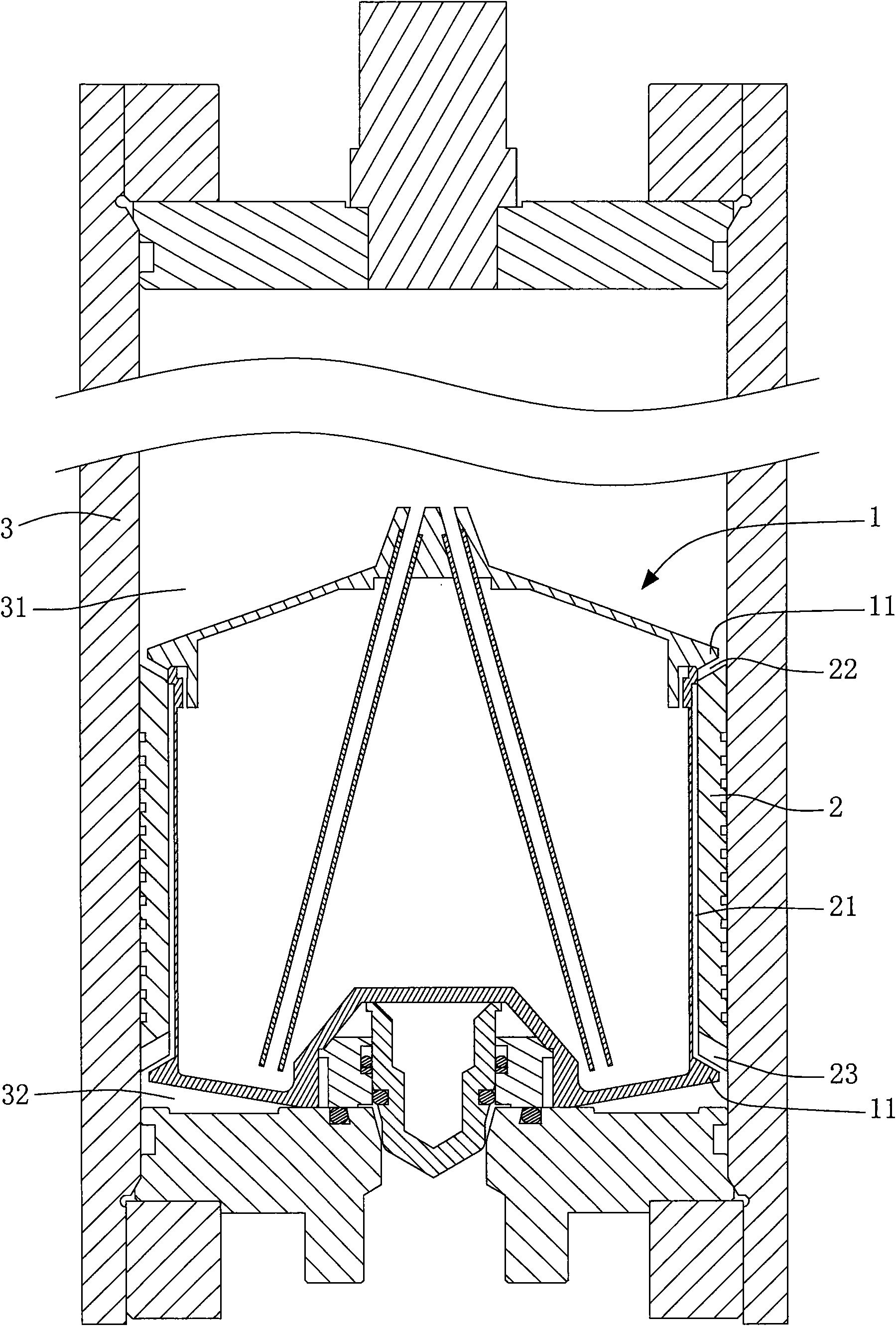
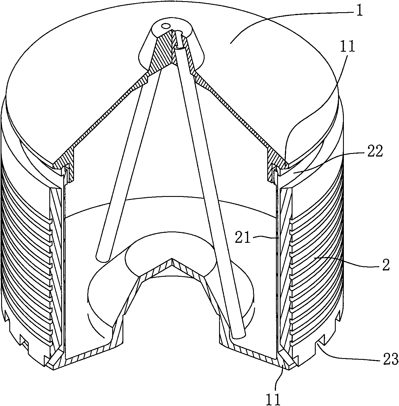
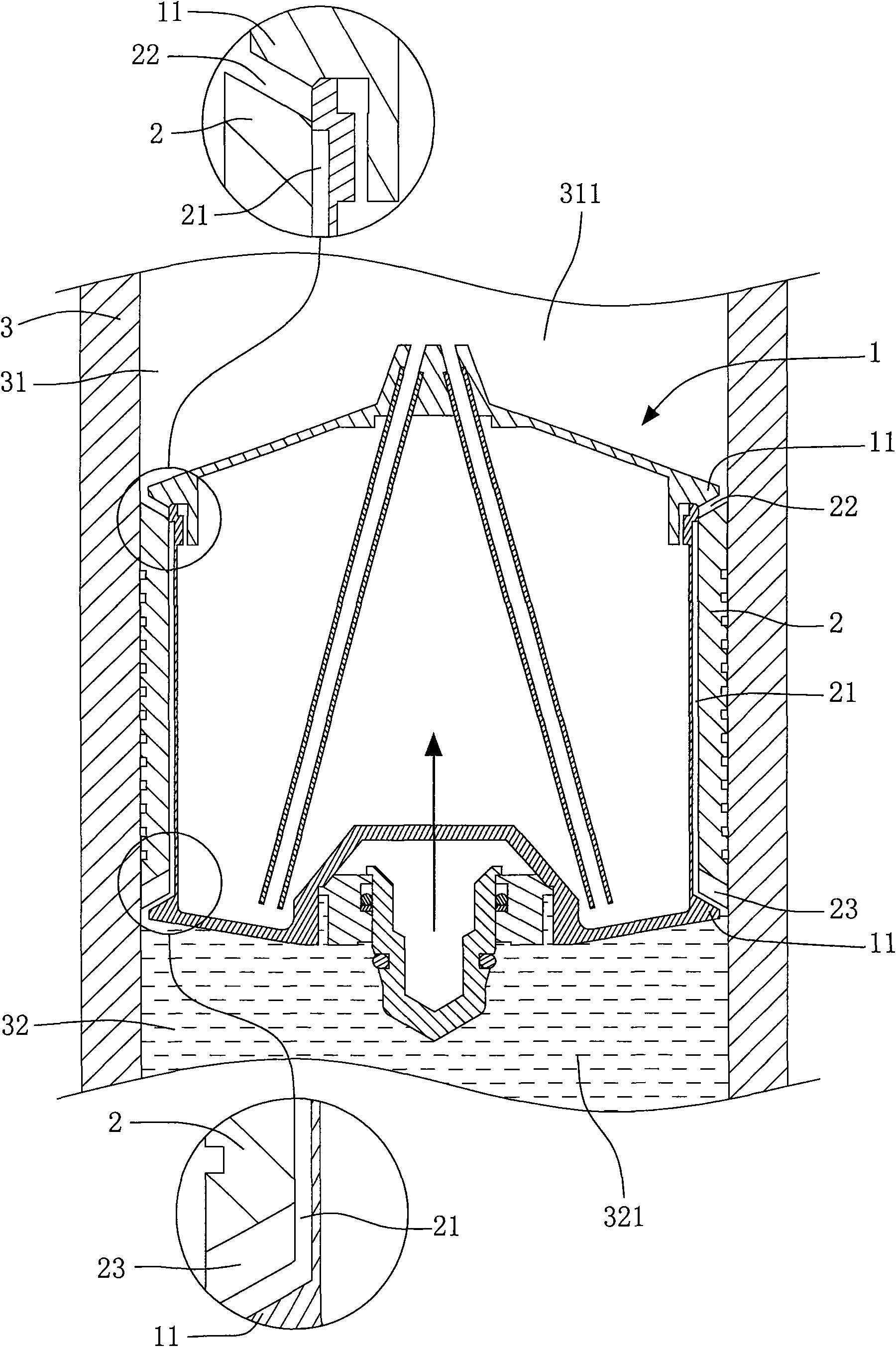
[0023] See first figure 1 and figure 2 As shown, the "accumulator floating ball sliding sleeve device" of the present invention includes a floating ball body 1, a ring sleeve 2 and a cylinder tube 3, wherein:

[0024] The floating ball body 1 is a hollow cylinder, and a ring 11 protrudes from its upper and lower edges.

[0025] The ring sleeve 2 is a ring cylinder combined on the vertical side periphery of the floating ball body 1, and the length of the ring sleeve is shorter than the floating ball body 1 and can slide between the upper and lower ring edges 11 without coming out. There is a gap 21 between the floating ball body 1 and the ring sleeve 2, and an annular upper opening 22 is formed at the upper end of the floating ball body 1 and the ring sleeve 2 to communicate with the gap 21; the lower en...


PUM


Abstract

The invention relates to a floating ball sliding sleeve device of an energy accumulator, which is mainly characterized in that a cylindrical floating ball body is arranged in a cylinder barrel and can slide up and down in the cylinder barrel; an annular sleeve is also assembled at the outer side of the floating ball body, and an appropriate gap for communicating liquid or gases is arranged between the annular sleeve and the floating ball body; upper through holes and lower through holes are respectively formed on the upper ends and the lower ends of the annular sleeve and the floating ball body; when the floating ball body slides upwards, the upper through holes and the lower through holes are all opened, the liquid or the gases can pass through the gap; and when the floating ball body slides downwards, the upper through holes are closed, and the lower through holes are opened to achieve the effect of a one-way valve.

Description

technical field [0001] The invention relates to a structural improvement of a pressure storage and release device, in particular to a structural improvement of a one-way valve effect between a floating ball body and a sliding sleeve. Background technique [0002] The function of the accumulator is to store the pressure in the hydraulic system and release it again when needed. Its main functions are as follows: [0003] 1. As an auxiliary power source: In the hydraulic system of intermittent work or periodic action cycle, the accumulator can store the excess pressure oil output by the hydraulic pump; when the system needs it, the pressure is released from the accumulator use. The accumulator can reduce the rated flow of the hydraulic pump, thereby reducing the power consumption of the motor and slowing down the temperature rise of the hydraulic system. [0004] 2. System pressure maintenance or emergency power source: For a system that needs to maintain a constant pressure ...

Claims


Application Information

Patent Timeline
Patent Type & Authority Applications(China)
IPC IPC(8): F15B1/04
CPCY02E60/15Y02E60/16
Inventor 郑文瑞
Owner QUNJI ENTERPRISES
Why Eureka
Try Eureka