Drive method and circuit for Polymer Dispersed Liquid Crystal (PDLC)

A technology of dispersed liquid crystal and driving method, which is applied in optics, instruments, nonlinear optics, etc., can solve problems such as screen flickering, screen flickering and jumping, etc., to eliminate screen flickering, reduce haze, and reduce drive The effect of power

Inactive Publication Date: 2010-12-29
北京众智同辉科技有限公司
View PDF2 Cites 17 Cited by
  • Summary
  • Abstract
  • Description
  • Claims
  • Application Information

AI Technical Summary

Problems solved by technology

The PDLC film is generally driven by a sinusoidal AC power frequency voltage. The disadvantage is that when the human eye observes the display screen of a display (including a projection display) that uses a scanning method through the PDLC film, due to the scanning frame rate of the display scanning system and the PDLC If the frequency of the AC working voltage or its multipl

Method used


Image

  • Drive method and circuit for Polymer Dispersed Liquid Crystal (PDLC)
  • Drive method and circuit for Polymer Dispersed Liquid Crystal (PDLC)
  • Drive method and circuit for Polymer Dispersed Liquid Crystal (PDLC)

Examples


Embodiment 1

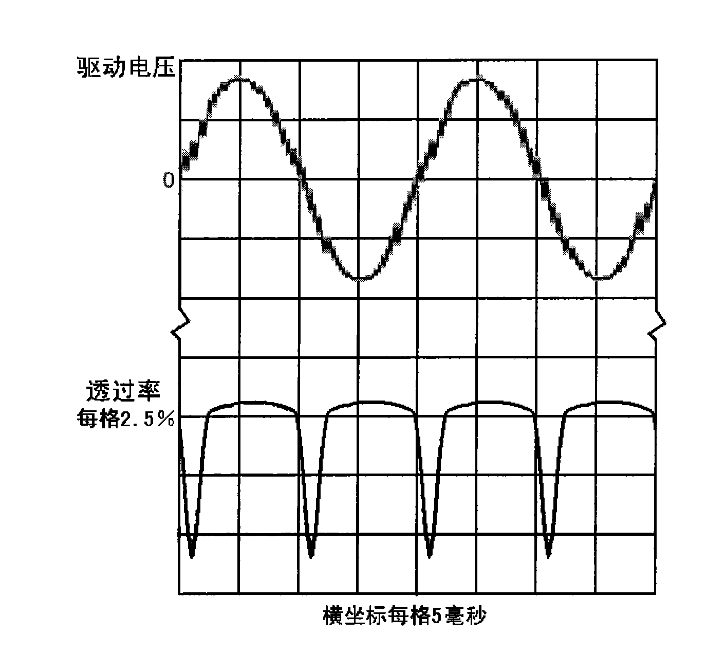
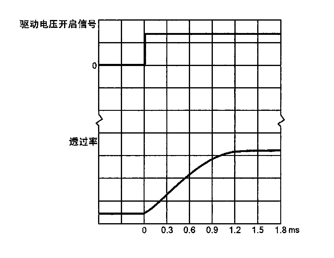
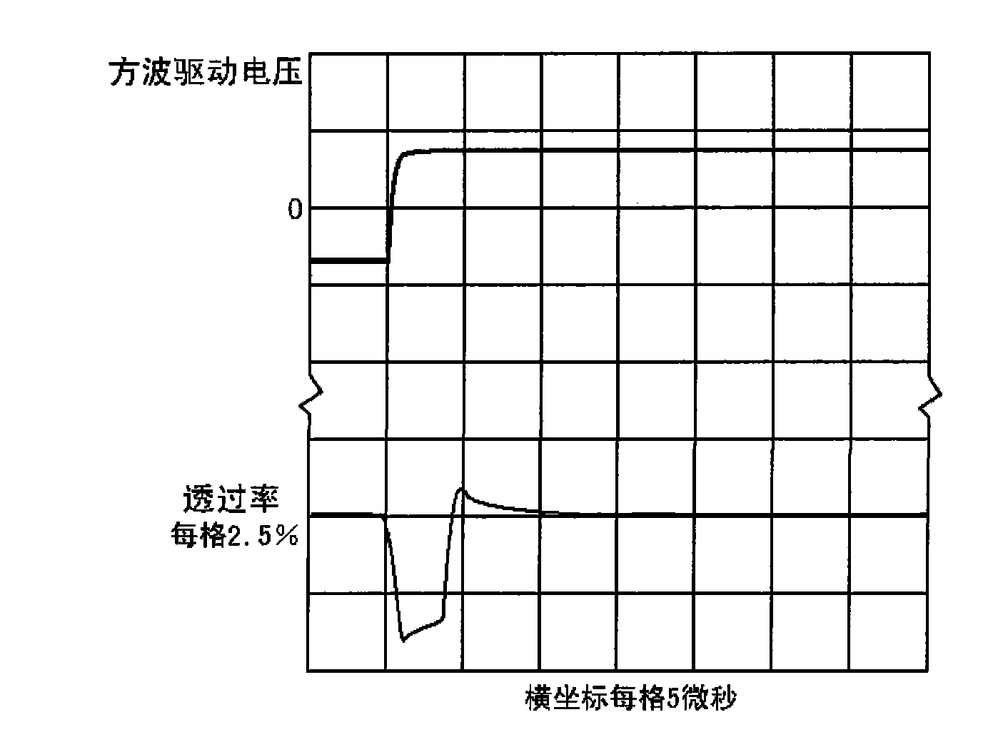
[0021] The driving method of the polymer-dispersed liquid crystal film of the present invention has a driving power supply that is electrically connected to two input electrodes of the polymer-dispersed liquid crystal film, and the voltage waveform that the driving power is applied to the input electrodes of the polymer-dispersed liquid crystal film It is a rectangular wave, and the front and rear edges of the rectangular wave should change rapidly, and its rising and falling time should be much shorter than the response time of opening and closing of the polymer dispersed liquid crystal film.

[0022] The polymer dispersed liquid crystal film of the present invention can be made into dimming glass, magic glass, electroluminescent liquid crystal atomized glass, etc., and the electroluminescent liquid crystal atomized glass in one embodiment of the present invention includes polymer dispersed liquid crystal film For the product, the structure of the electroluminescent liquid cry...

Embodiment 2

[0026] see Figure 4 , Figure 5 , the driving circuit of the polymer dispersed liquid crystal film of the present invention has a driving power source electrically connected to two input electrodes of the polymer dispersed liquid crystal film, and the driving power source includes a rectangular wave generating circuit, a driver stage, a double-arm bridge push-pull output circuit; the double-arm bridge push-pull output circuit includes four field effect transistors or insulated gate bipolar transistors; wherein the drain of the field effect transistor T1 is electrically connected to the positive pole of the power supply, and the source of the transistor T1 is connected to the transistor T2 The drain is electrically connected, the source of the transistor T2 is connected to the power ground; the drain of the transistor T3 is electrically connected to the positive pole of the power supply, the source of the transistor T3 is electrically connected to the drain of the transistor T...


PUM


Abstract

The invention relates to a drive method and circuit for Polymer Dispersed Liquid Crystal (PDLC). A drive power supply is electrically connected with two input electrodes of the polymer dispersed liquid crystal film; the waveform of voltage applied to the input electrodes of the polymer dispersed liquid crystal film by the drive power supply is rectangular wave; and the front and rear edges of the rectangular wave are quickly changed, and the ascending and descending time of the rectangular wave is far less than the opening and closing response time of the polymer dispersed liquid crystal film. The drive power supply comprises a rectangular wave generating circuit, a drive stage and a double-arm bridge type pull output circuit, wherein the double-arm bridge type pull output circuit comprises four field effect transistors. The method effectively eliminates the screen splash phenomenon, does not need to drive the frequency of the alternating voltage of the PDLC film to synchronize with the frame frequency of a display observed through the PDLC film by adopting a scanning mode, improves the transmittance of the transparent state of the PDLC film and reduces the haze.

Description

technical field [0001] The invention relates to a driving method and circuit of a polymer-dispersed liquid crystal film. The driving method adopts an AC voltage waveform whose voltage quickly crosses zero, and its frequency and phase can be compared with those passed through the polymer-dispersed liquid crystal film. The scanning frame rate of the monitor using the scanning method is observed regardless of the scanning frame rate. Driving the polymer-dispersed liquid crystal film in this way can eliminate the flickering phenomenon of viewing other types of display screens through the polymer-dispersed liquid crystal film, increase the transmittance of the polymer-dispersed liquid crystal film in a transparent state, and reduce the haze. technical background [0002] US Patent No. 4,671,618 discloses a method for making phase-separated polymer-dispersed liquid crystals. This method can be used to make polymer-dispersed liquid crystal films and PALC films, which are collective...

Claims


Application Information

Patent Timeline
IPC IPC(8): G02F1/133G02F1/1334
Inventor 李裕宽张维平高建谧赵勤郭川
Owner 北京众智同辉科技有限公司
Why Eureka
Try Eureka