Continuous transformer
A technology of transformers and drums, applied in the field of electric power, can solve problems such as waste of resources, difficulty in adapting to many different electrical equipment, and low versatility, and achieve the effect of good versatility
- Summary
- Abstract
- Description
- Claims
- Application Information
AI Technical Summary
Problems solved by technology
Method used
Image


Examples
Embodiment Construction
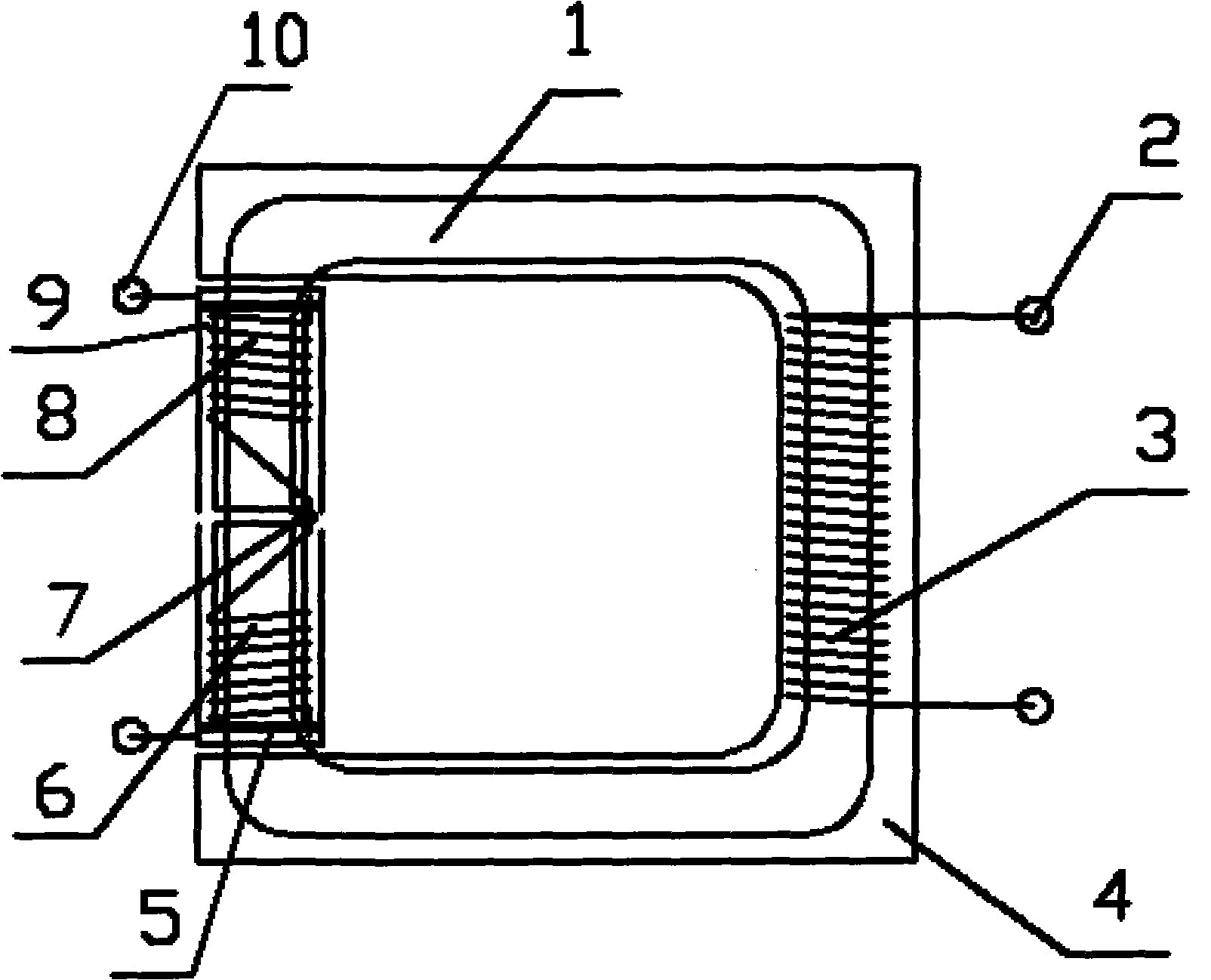
[0012] Below in conjunction with accompanying drawing and embodiment the present invention is further described:
[0013] In the embodiment shown in the drawings, the continuous transformer includes an iron core 1, an output terminal 2, an output coil 3, a casing 4, a metal ring 5, a first input coil 6, a threading terminal 7, a second input coil 8, a drum 9. The input terminal 10, the iron core 1 is a closed circuit, the output coil 3 is wound on one side, the two ends of which are connected to the output terminal 2, and the two rotating cylinders are installed on the other side 9. The two drums 9 can freely rotate on the iron core 1, one of the drums 9 is wound with the first input coil 6, and the other drum 9 is wound with the second coil 9. Input coil 8, the winding directions of the two coils are opposite, viewed from the same side, one is clockwise and the other is counterclockwise, the two coils pass through the threading wires fixed on the iron core 1 at the center of ...
PUM
 Abstract
Description
Claims
Application Information
 - Generate Ideas
- Intellectual Property
- Life Sciences
- Materials
- Tech Scout
- Unparalleled Data Quality
- Higher Quality Content
- 60% Fewer Hallucinations
Browse by: Latest US Patents, China's latest patents, Technical Efficacy Thesaurus, Application Domain, Technology Topic, Popular Technical Reports.
© 2025 PatSnap. All rights reserved.Legal|Privacy policy|Modern Slavery Act Transparency Statement|Sitemap|About US| Contact US: help@patsnap.com