Regulation method for a cold-rolling train with complete mass flow regulation

An adjustment method, technology for cold rolling mills, applied in the direction of driving devices for metal rolling mills, rolling mill control devices, metal rolling, etc., capable of solving problems such as slow monitoring adjustments, insufficient corrections, etc.

Active Publication Date: 2010-12-29
PRIMETALS TECH GERMANY
View PDF1 Cites 8 Cited by
  • Summary
  • Abstract
  • Description
  • Claims
  • Application Information

AI Technical Summary

Problems solved by technology

For the most common mode of operation, that is, the last stand of the cold rolling mill train is working in the tempering operation (that is to say, only working with a small thickness reduction, such as 1% to 2%). However, slow monitoring adjustments at the exit of the cold rolling mill train in the most common mode of operation described can only insufficiently correct these thickness errors

Method used


Image

  • Regulation method for a cold-rolling train with complete mass flow regulation
  • Regulation method for a cold-rolling train with complete mass flow regulation
  • Regulation method for a cold-rolling train with complete mass flow regulation

Examples


Embodiment Construction

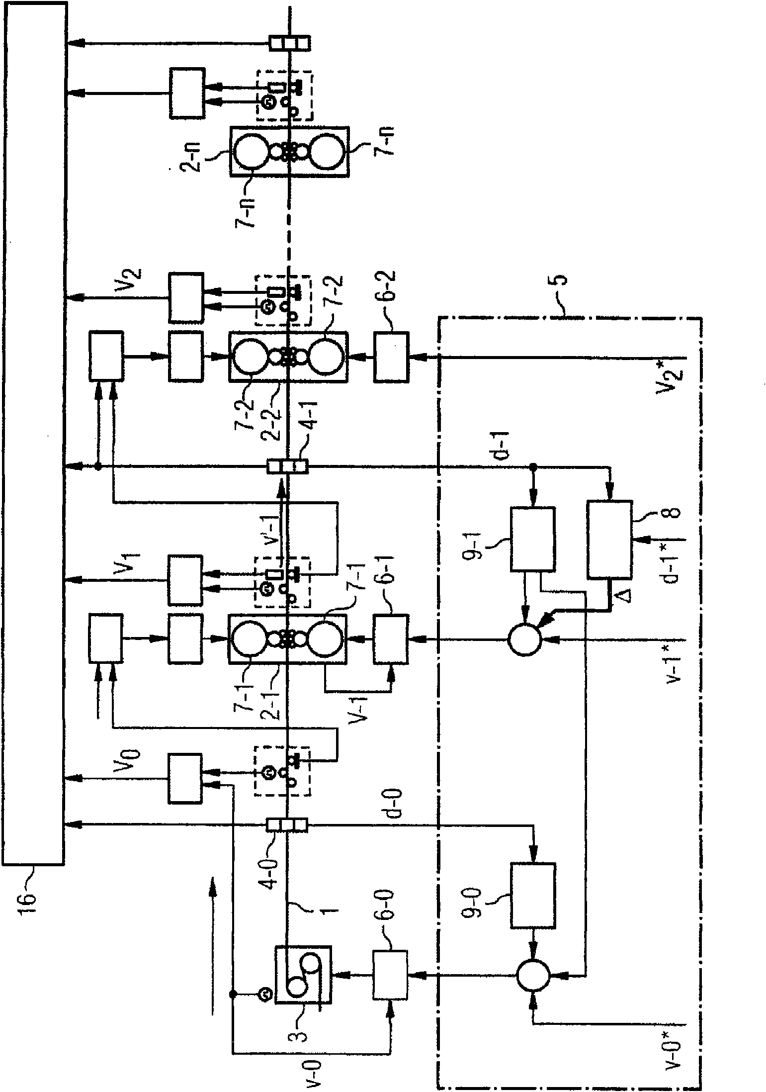
[0045] according to figure 1 , the cold-rolling mill row for rolling the cold-rolled steel strip 1 has a plurality of stands 2 . The frame 2 is passed through by the cold-rolled steel strip 1 successively.

[0046]Wherever necessary, place a number or letter n accordingly following rack 2 with a hyphen below. The number "1" here stands for the first passing rack 2, the number "2" stands for the next passing rack 2, and the letter "n" stands for the last passing rack 2. The same processing is also to be understood in connection with other elements and variables marked with reference numerals, if this is necessary.

[0047] Furthermore, the cold rolling train has a strip conveyor 3 . The strip conveying device 3 is arranged in front of the first passing frame 2-1. The strip conveying device 3 according to figure 1 Structured as S roll group. This strip conveyor 3 is partly referred to below as "stand zero". Correspondingly, elements and variables associated with the strip...


PUM


Abstract

A cold-rolling train comprises a plurality of rolling stands (2) through which a cold strip (1) passes in succession and a strip feeding device (3) located prior to the first passed-through rolling stand (2-1). A nulled setpoint speed (v-0*) is sent to the strip feeding device (3) so that the strip feeding device (3) feeds the cold strip (1) to the first passed-through rolling stand (2-1) at a nulled actual speed (v-0) corresponding to the nulled setpoint speed (v-0*). A first setpoint speed (v-1*) is sent to the first passed-through rolling stand (2-1) so that rolls (7-1) of the first passed-through rolling stand (2-1) rotate at a first actual speed (v-1) corresponding to the first setpoint speed (v-1*). Between the first passed-through rolling stand (2-1) and the rolling stand (2-2) passed through next is a first thickness detection device (4-1), by means of which a first actual thickness (d-1) of the cold strip (1) is detected. A base output signal (delta) is determined using the first actual thickness (d-1) and a first setpoint thickness (d-1*), said base output signal being used to adjust the first setpoint speed (v-1*), but not the nulled setpoint speed (v-0*), so that the first actual thickness (d-1) is conformed to the first setpoint thickness (d-1*). Between the strip feeding device (3) and the first passed-through rolling stand (2-1) is a nulled thickness detection device (4-0), by means of which a nulled actual thickness (d-0) of the cold strip (1) is detected. The nulled setpoint speed (v-0*) is adjusted by way of a nulled feed-forward controller (9-0) in such a way that the product is adjusted to a setpoint mass flow by the nulled setpoint speed (v-0*) and the nulled actual thickness (d-0).

Description

technical field [0001] The invention relates to an adjustment method for a cold-rolling train having a plurality of stands through which cold-rolled strip passes one after the other and a strip conveying device arranged in front of the first passing stand, [0002] - wherein the zeroth rated speed is input to said strip conveying device, so that said strip conveying device conveys the cold rolled strip at a zeroth actual speed corresponding to said zeroth rated speed to the first passing frame, [0003] - wherein a first nominal speed is input to said first passing stand such that the rolls of said first passing stand rotate at a first actual speed corresponding to said first nominal speed, [0004] - wherein the first actual thickness of the cold-rolled strip is detected by means of a first thickness detection device arranged between said first passing stand and the next passing stand, [0005] - wherein the basic output signal is ascertained from the first actual thickness...

Claims


Application Information

Patent Timeline
Patent Type & Authority Applications(China)
IPC IPC(8): B21B37/16
CPCB21B38/04B21B37/165B21B1/28B21B2275/04B21B37/54B21B37/46B21B2261/04
Inventor H-J·费尔克尔
Owner PRIMETALS TECH GERMANY
Why Eureka
Try Eureka