
Precision control method for laser directional energy deposition shape

A precision control and laser technology, applied in processing and manufacturing, additive manufacturing, manufacturing auxiliary devices, etc., can solve the problems of affecting powder, difficult to ensure the overall shape accuracy of products, affecting product shape accuracy, etc., to achieve the effect of improving dimensional accuracy

Active Publication Date: 2022-07-08
中国人民解放军32181部队
View PDF6 Cites 0 Cited by
  • Summary
  • Abstract
  • Description
  • Claims
  • Application Information

AI Technical Summary

Problems solved by technology

At present, the main reason for affecting the shape accuracy in the laser directed energy deposition process is that the accumulation of molten powder cannot be accurately controlled. Affected by factors such as laser power, powder feeding rate, and powder feeding nozzle moving speed, the additive manufacturing of each layer There is a certain gap between the height (that is, the value in the Z direction) and the ideal value, which will affect the shape accuracy of the product in the Z direction
At the same time, the above factors will also affect the shape accuracy of the powder in the X and Y directions, so it is difficult to guarantee the overall shape accuracy of the product

Method used

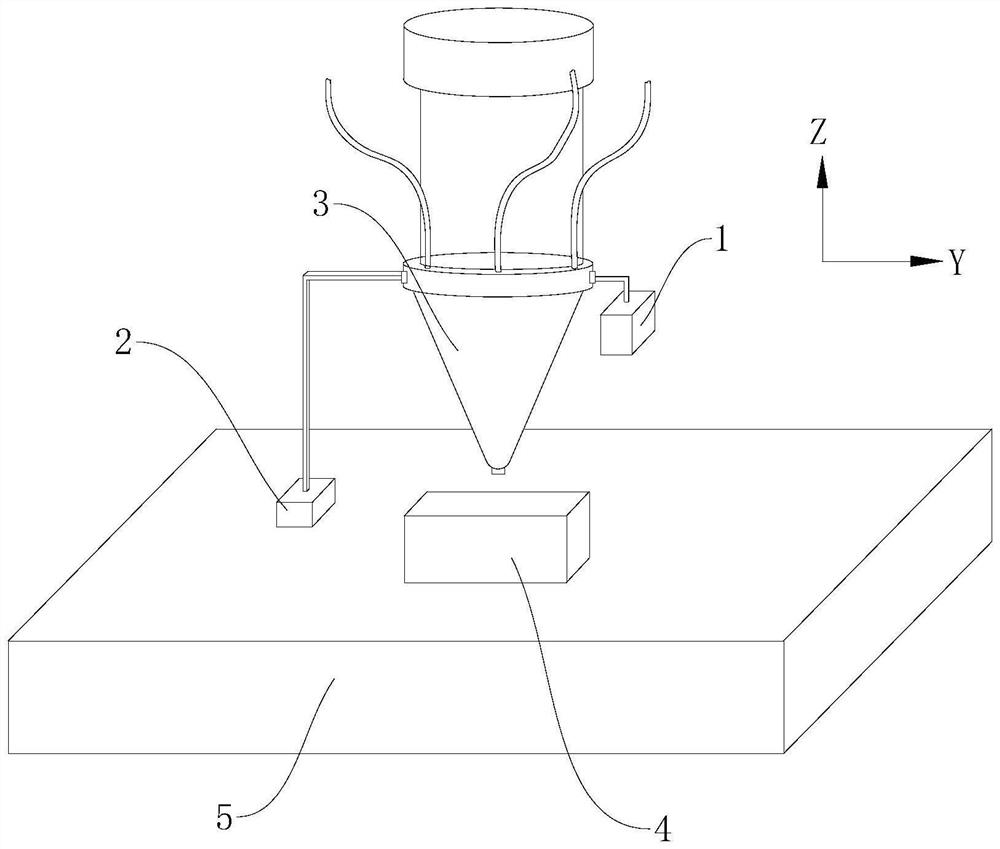
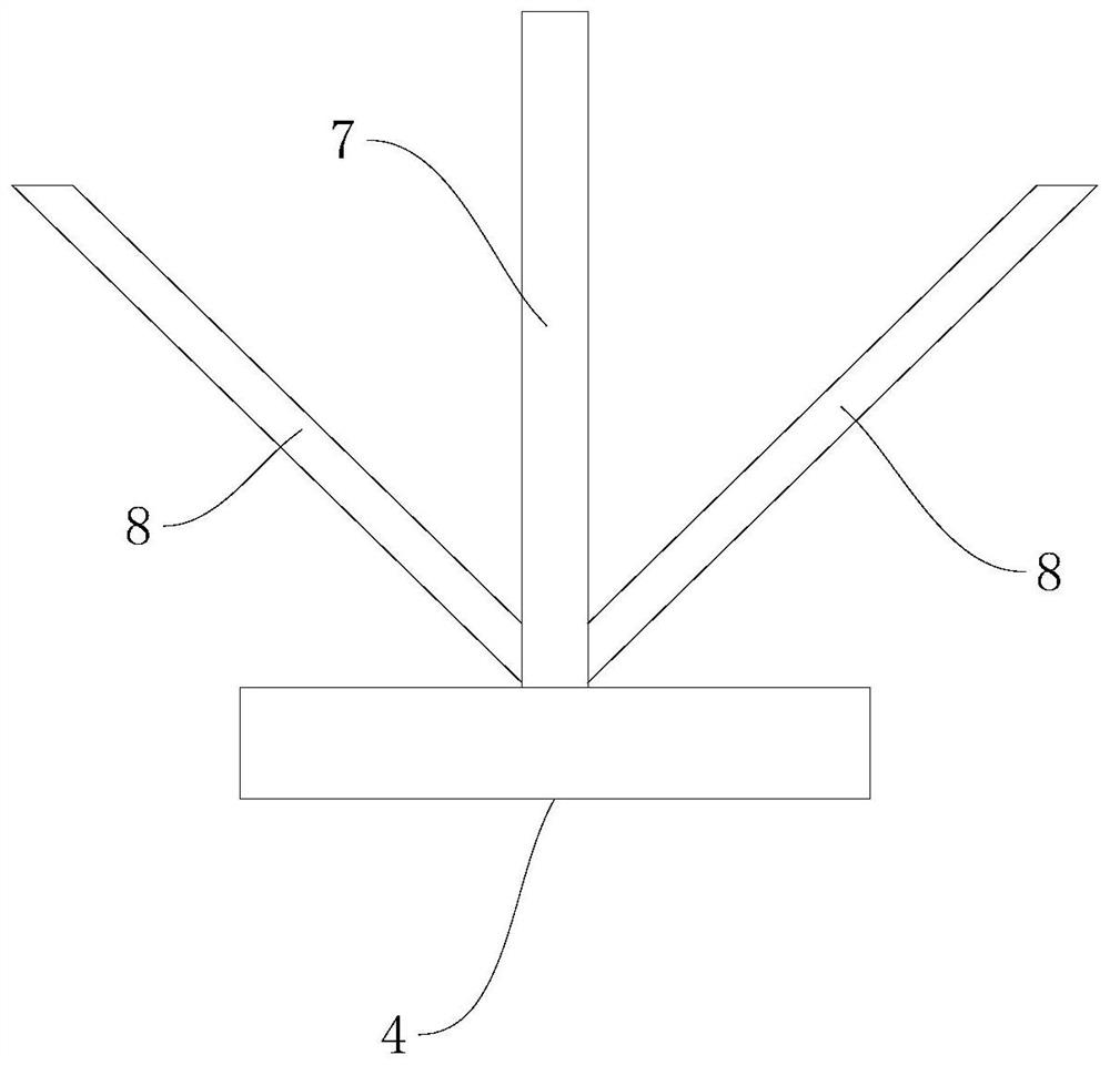
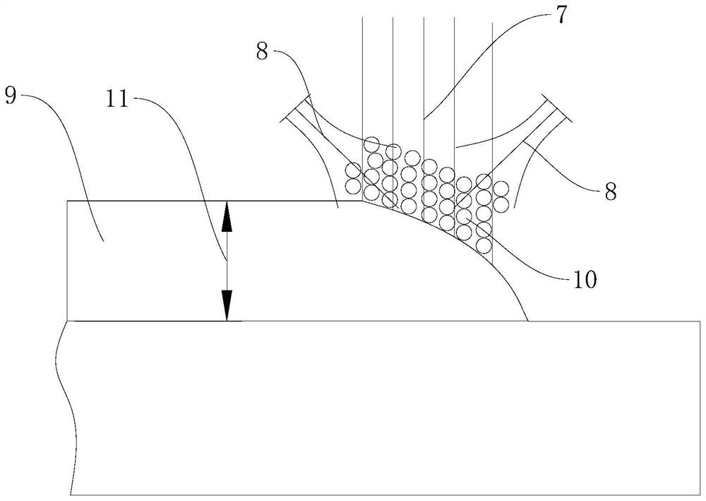

Image

  • Precision control method for laser directional energy deposition shape
  • Precision control method for laser directional energy deposition shape
  • Precision control method for laser directional energy deposition shape

Examples


Embodiment Construction

[0040] In order to make the technical problems, technical solutions and beneficial effects to be solved by the present invention clearer, the present invention will be further described in detail below with reference to the accompanying drawings and embodiments. It should be understood that the specific embodiments described herein are only used to explain the present invention, but not to limit the present invention.

[0041]It should be noted that when an element is referred to as being "disposed on" another element, it can be directly on the other element or indirectly on the another element. It is to be understood that the terms "length", "width", "upper", "lower", "front", "rear", "top", "bottom", "inner", "outer" etc. refer to the orientation or The positional relationship is based on the orientation or positional relationship shown in the accompanying drawings, which is only for the convenience of describing the present invention and simplifying the description, rather ...


PUM


Abstract

The invention provides a laser orientation energy deposition shape precision control method. The method comprises the following steps that an actual height value and an actual edge thickness value of a workpiece are acquired and converted through a first distance measuring sensor and a second distance measuring sensor; calculating a height difference value and an edge thickness difference value; and the workpiece is compensated in the lower layer deposition. According to the laser orientation energy deposition shape precision control method provided by the invention, the actual height value of the workpiece is acquired and converted through the first distance measuring sensor, and the actual edge thickness value of the workpiece is acquired and converted through the second distance measuring sensor; the actual height value and the actual edge thickness value are compared with a preset height value and a preset edge thickness value which are obtained through simulation calculation respectively, the difference value is calculated, the height difference value and the edge thickness difference value are obtained, compensation is conducted by adjusting machining parameters in lower layer deposition, and accurate control over the forming process is achieved; the shape precision of the workpiece is close to a preset value, and the size precision of workpiece machining is improved.

Description

technical field [0001] The invention belongs to the technical field of advanced manufacturing, and more particularly, relates to a shape precision control method of laser directional energy deposition. Background technique [0002] Laser directed energy deposition uses a laser to melt powders. The way the powder feedstock is deposited and melted makes it easier to scale to larger additively manufactured parts. Laser directed energy deposition has high energy density and fast cooling non-equilibrium solidification characteristics, so that the prepared solidified structure is finer and the mechanical properties of the solidified structure are better. In addition, laser directed energy deposition adopts the method of synchronous powder feeding, and the production efficiency is high, so this method is widely used in petroleum, chemical, aerospace, biomedicine and other fields. [0003] The shape accuracy of additive manufacturing is a key factor affecting the molding quality. ...

Claims


Application Information

Patent Timeline
Patent Type & Authority Applications(China)
IPC IPC(8): B29C64/393B29C64/153B22F10/85B22F10/31B22F10/366B33Y50/02
CPCB29C64/393B29C64/153B22F10/85B22F10/31B22F10/366B33Y50/02Y02P10/25
Inventor 张连武孙江生黄胜赵晔吕艳梅王正军梁伟杰黄文斌李万领蔡娜连光耀张连重
Owner 中国人民解放军32181部队
Learn More