Method for forming deposited film

An evaporation film and evaporation technology, applied in vacuum evaporation plating, sputtering plating, ion implantation plating, etc., can solve problems such as wrinkles, decrease in charge-discharge cycle characteristics, and peeling of current collectors and active material layers. , to achieve the effect of mass productivity and relaxation of expansion stress

Inactive Publication Date: 2010-12-29
PANASONIC CORP
View PDF6 Cites 11 Cited by
  • Summary
  • Abstract
  • Description
  • Claims
  • Application Information

AI Technical Summary

Problems solved by technology

[0004] However, even if the vacuum process is used, the current collector and the active material layer may peel off due to the expansion and contraction of the active material during charging and discharging, or wrinkles may appear on the current collector due to stress, which becomes a problem for charging and discharging. Main cause of degradation of cycle characteristics

Method used


Image

  • Method for forming deposited film
  • Method for forming deposited film
  • Method for forming deposited film

Examples


no. 1 approach

[0069] **** Implementation of single-sided V ***

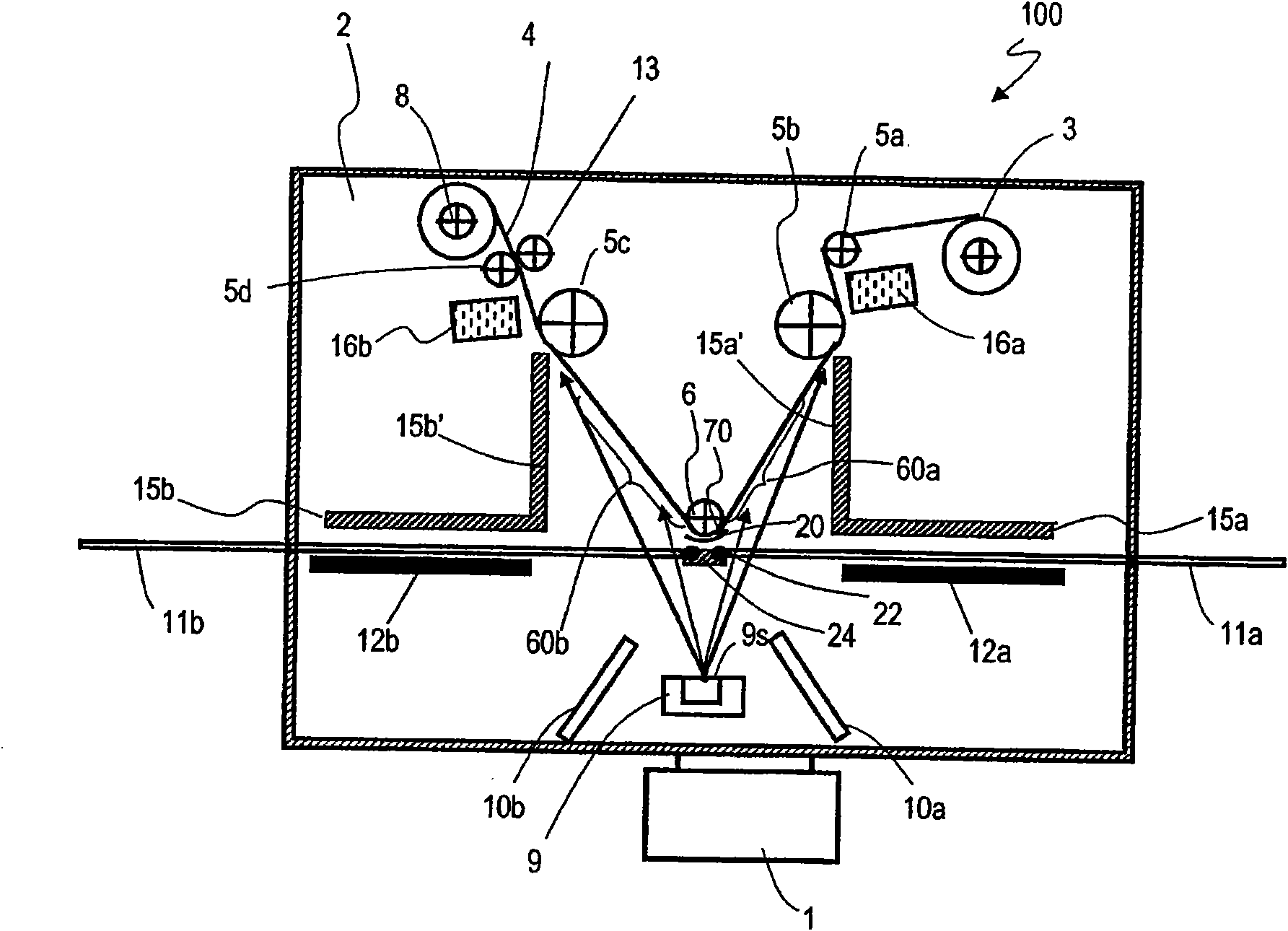
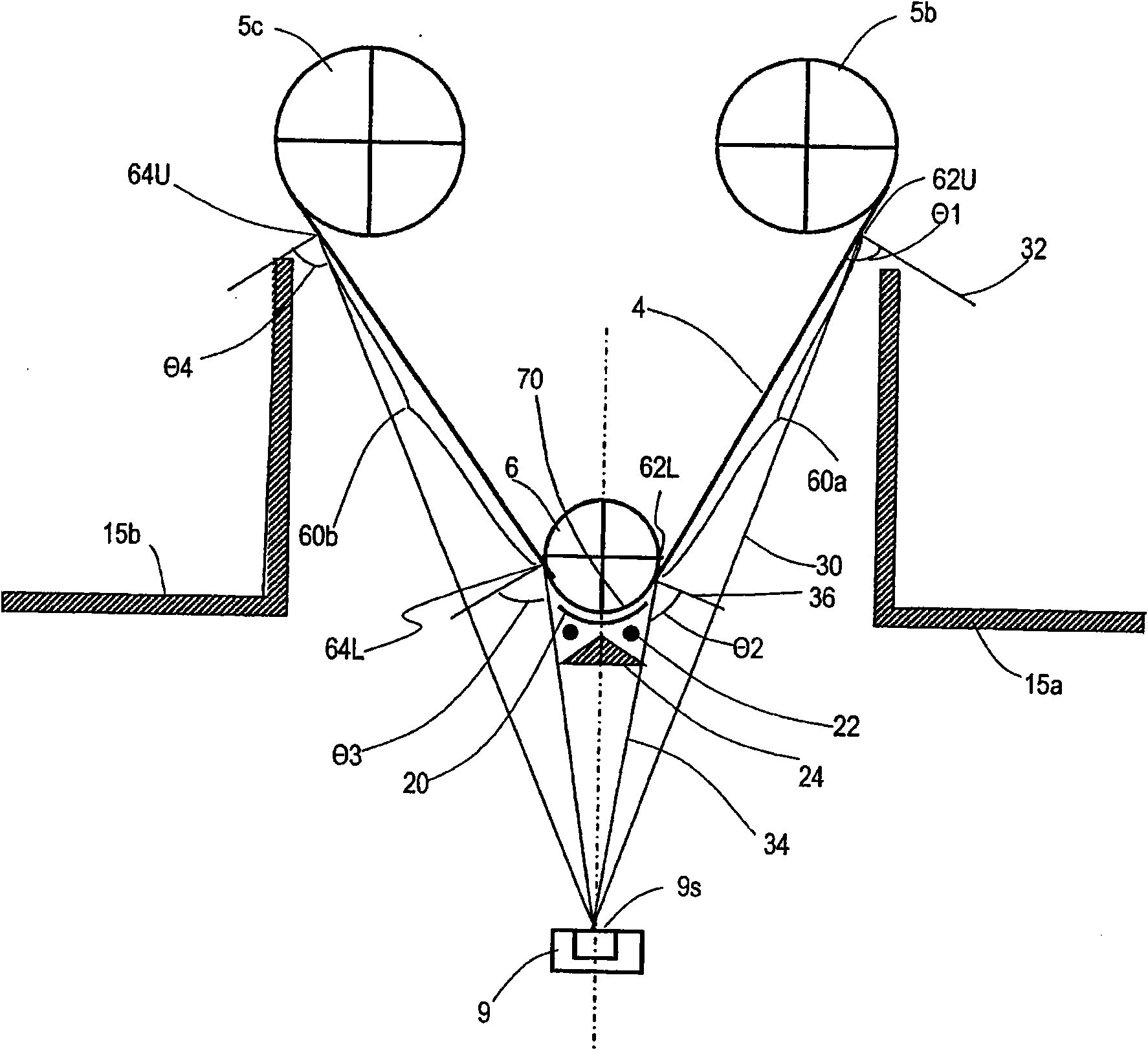
[0070] In the vapor deposition apparatus of the present embodiment, the sheet-shaped substrate is conveyed in the chamber so as to protrude from the evaporation source, and vapor deposition is performed on both sides of the portion that is the apex of the protrusion. That is, this embodiment has a V-shaped substrate path (V-shaped path).

[0071]

[0072] First, refer to figure 1 . figure 1 is a cross-sectional view schematically showing the vapor deposition device according to the first embodiment of the present invention. The vapor deposition apparatus 100 includes: a chamber (vacuum tank) 2; an exhaust pump 1 provided outside the chamber 2 for exhausting the chamber 2; and introducing oxygen into the chamber 2 from the outside of the chamber 2, etc. The gas introduction pipes 11a and 11b of the gas. The inside of the chamber 2 is provided with: an evaporation source 9 for evaporating the evaporation material; a conv...

no. 2 approach

[0142] ***Single-sided W Implementation Mode***

[0143] Next, a vapor deposition apparatus according to a second embodiment of the present invention will be described with reference to the drawings. In the present embodiment, two V-shaped substrate pathways (V-shaped pathways) described in the first embodiment are provided in the vapor-deposition-capable region in the chamber, thereby forming a total of four vapor-deposition-capable regions.

[0144] Image 6 is a cross-sectional view schematically showing a vapor deposition device according to a second embodiment of the present invention. For simplicity, with figure 1 The same constituent elements of the illustrated vapor deposition apparatus 100 are denoted by the same reference numerals, and description thereof will be omitted. Image 6 The illustrated vapor deposition apparatus 200 is provided with a conveyance unit, thereby defining a conveyance path of the substrate 4 . The conveyance section includes first and secon...

no. 3 approach

[0174] ***W1 (double-sided) implementation***

[0175] Hereinafter, a vapor deposition apparatus according to a third embodiment of the present invention will be described with reference to the drawings. In this embodiment, similarly to Embodiment 2, a W-shaped substrate path (W-shaped path) is provided, and a total of four vapor deposition capable regions (first to fourth vapor deposition capable regions) 60 a to 60 d are formed. Wherein, the conveying part of the present embodiment is configured to turn over the substrate 4 after passing through the first and second vapor-deposition regions 60a, 60b, and guide it to the third and fourth vapor-deposition regions 60c, 60d. It is different from the second embodiment.

[0176] Figure 7 It is a sectional view illustrating the vapor deposition apparatus of this embodiment. For simplicity, with Image 6 The same constituent elements of the illustrated vapor deposition apparatus 200 are denoted by the same reference numerals, an...


PUM

PropertyMeasurementUnit
lengthaaaaaaaaaa

Abstract

Disclosed is a vacuum vapor deposition device with excellent series production properties, which simultaneously forms the collector lead formation area and the electrode active material area of a lithium secondary battery. With shutters (12a, 12b) in the closed state, a substrate (4) wound onto a first roll (3) is paid out and transported towards a second roll (8), and stopped upon arriving at first and second vapor deposition zones (60a, 60b). Here, the shutter (12a) is opened and a vapor deposition material in the crucible of a vaporization source (9) is vaporized and delivered to the surface of the substrate (4) positioned at the first vapor deposition zone (60a). Thus, a first vapor deposition film layer is formed on the surface of the substrate (4). After vapor deposition has been performed for a specified time onto the substrate (4), the shutter (12a) is closed. Next, the substrate (4) is transported again and the portion on which vapor deposition was formed in the first vapor deposition zone (60a) is stopped at the position of the second vapor deposition zone (60b). The shutters (12a, 12b) are opened and vapor deposition is performed again, forming a first layer in the first vapor deposition zone (60a) and forming a second vapor deposition film layer with a different growth orientation than that of the first layer on top of the first layer in the second vapor deposition zone (60b).

Description

technical field [0001] The present invention relates to a method for forming a vapor-deposited film. Background technique [0002] In recent years, along with the high performance and multifunctionalization of mobile devices, high capacity of secondary batteries serving as their power sources has been demanded. Non-aqueous electrolyte secondary batteries have attracted attention as secondary batteries that can satisfy this requirement. In order to increase the capacity of non-aqueous electrolyte secondary batteries, it has been proposed to use silicon (Si), germanium (Ge), tin (Sn) and the like as electrode active materials (hereinafter, abbreviated as "active materials"). Generally, an electrode for a nonaqueous electrolyte secondary battery using such an electrode active material (hereinafter, simply referred to as "electrode") is formed by coating a slurry containing an electrode active material, a binder, and the like on a collector ( Hereinafter, it is referred to as ...

Claims


Application Information

Patent Timeline
Patent Type & Authority Applications(China)
IPC IPC(8): C23C14/24C23C14/56H01M4/04H01M4/50
CPCH01M10/058H01M10/0525C23C14/562C23C14/225Y02E60/10
Inventor 冈崎祯之本田和义
Owner PANASONIC CORP
Why Eureka
Try Eureka