

Novel urban electric power composite track traffic system
A technology of rail transit and electric rail, which is applied in the direction of electric rail, elevated railway system without suspension vehicles, elevated railway, etc. It can solve the problems of interfering with road traffic, occupying a large amount of road resources, and low efficiency, so as to achieve high-efficiency public transportation, Low footprint, low cost effect
- Summary
- Abstract
- Description
- Claims
- Application Information
AI Technical Summary
Problems solved by technology
Method used
Image

Examples
Embodiment Construction
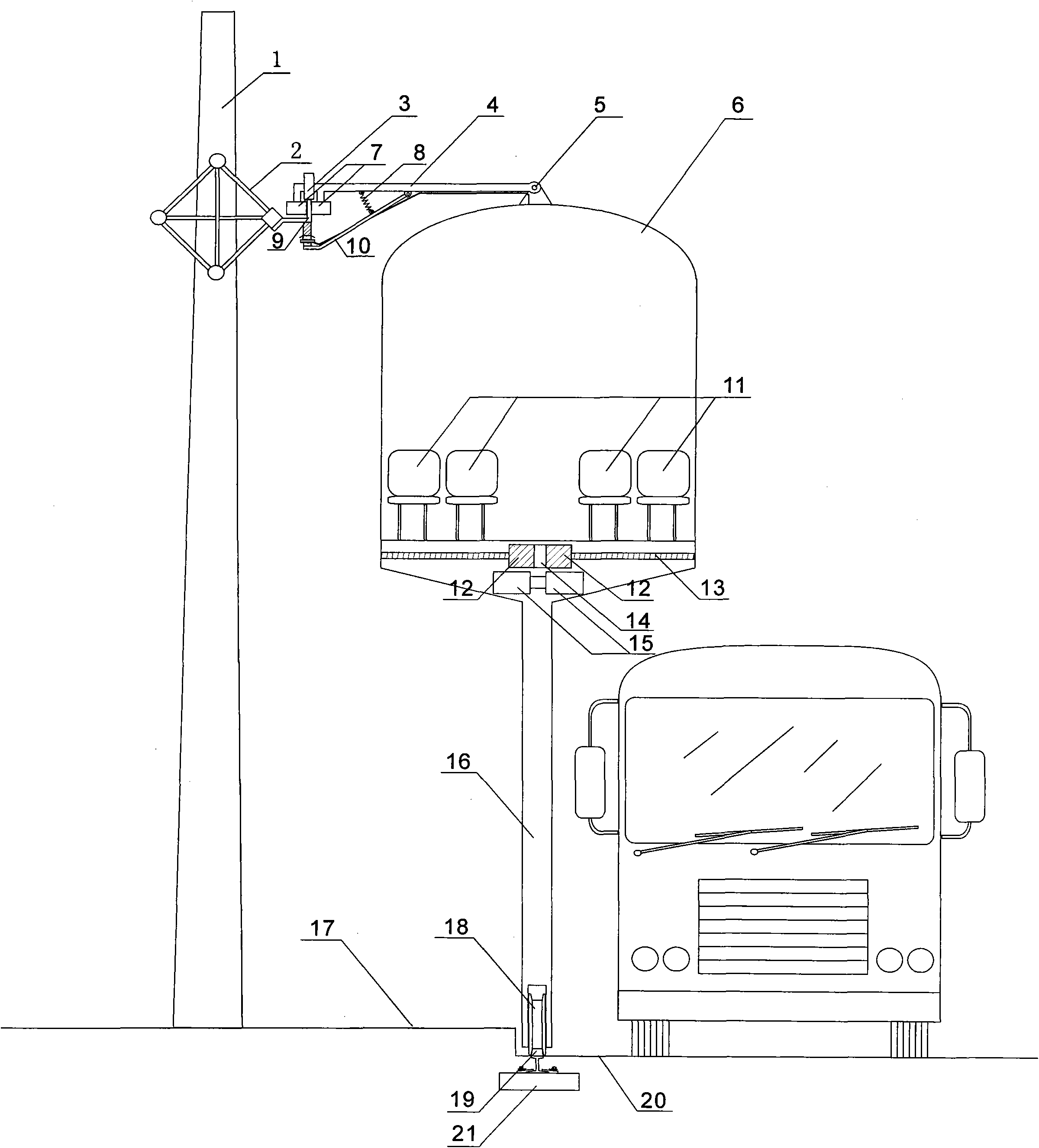
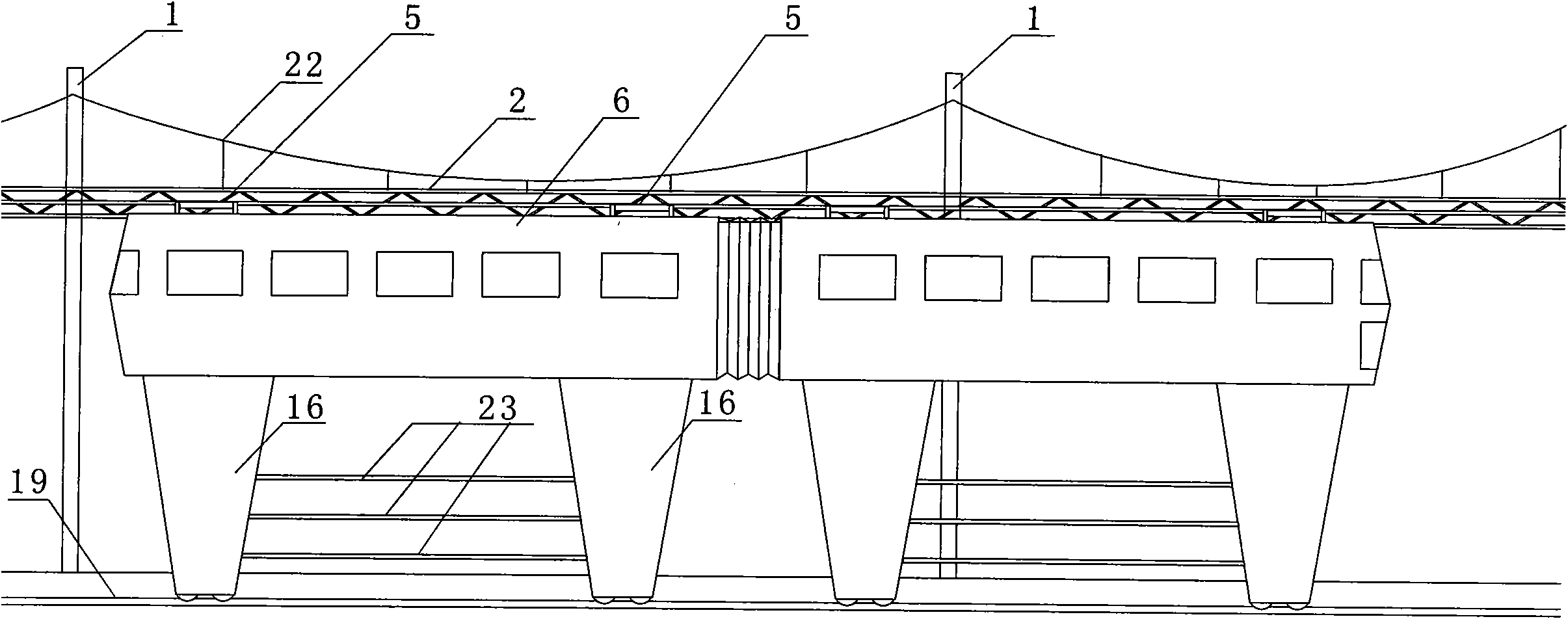
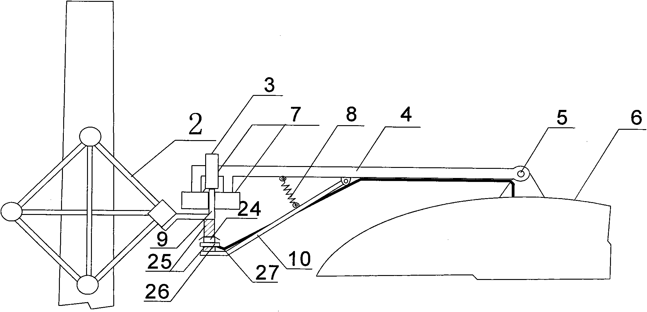
[0010] like figure 1 , at the junction of the street surface (20) and the sidewalk (17), shallowly bury sleepers (21), so that the ground bearing rails (19) laid on the sleepers (21) are almost flush with the street surface (20) (slightly higher 20~30mm), set up the auxiliary track column (1) along the road at appropriate positions on the sidewalk (17), and the auxiliary track frame (2) is installed on the upper end of the auxiliary track column (1), in order to ensure that the auxiliary track frame (2) Straight, set the auxiliary track frame auxiliary sling (22) at the top between the auxiliary track columns (1) (such as figure 2 ), the rigid auxiliary track is set up in the air, and the height distance is compatible with the auxiliary rocker arm (4) on the upper part of the electric rail vehicle body, and is parallel to the ground bearing rail, and the lower part of the rigid auxiliary track (9) is installed with an insulator (25). Rail (24) (such as image 3 ) The entire...
PUM
 Abstract
Description
Claims
Application Information