Construction method of dewatering well in underground concrete structure

A technology of concrete structure and construction method, which is applied in the direction of basic structure engineering, construction, etc., can solve the problems that the sealing concrete does not reach the strength, the new and old concrete are not tightly connected, and the structure leaks, etc., so as to avoid structural leakage, reduce groundwater pressure, and seal treatment. simple effect

Inactive Publication Date: 2011-01-05
TIANJIN 20 CONSTR
View PDF3 Cites 22 Cited by
  • Summary
  • Abstract
  • Description
  • Claims
  • Application Information

AI Technical Summary

Problems solved by technology

Due to the high pressure of groundwater, a slight omission in this construction method will cause water leakage in the structure due to improper sealing of the drainage pipe.
Especially when the groundwater level is high and the bearing pressure is high, the sealing concrete is often

Method used


Image

  • Construction method of dewatering well in underground concrete structure
  • Construction method of dewatering well in underground concrete structure
  • Construction method of dewatering well in underground concrete structure

Examples


Embodiment 1

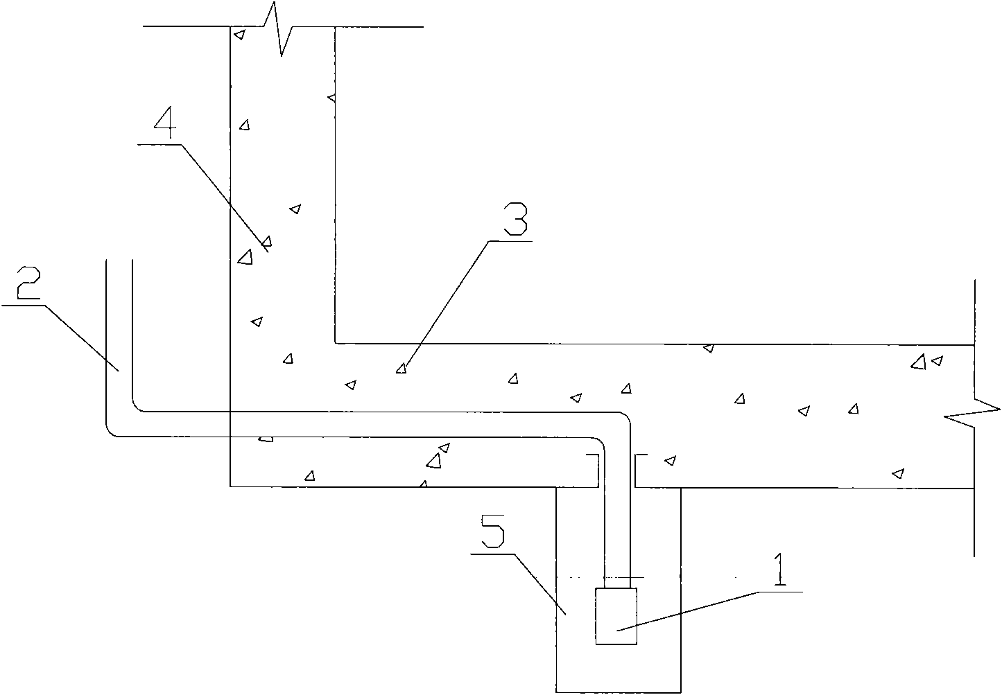
[0036] Such as figure 2 As shown, when the building adopts an underground independent wall, that is, when there is a certain space between the outside of the wall and the foundation pit, the outside of the underground concrete structure can support formwork. Firstly, the foundation pit is sloped and excavated, and a dewatering well 5 is set at the bottom of the foundation pit. A downwater pipe 2 is arranged in the dewatering well 5, and the lower port of the downwater pipe 2 is connected to the water pump 1, and the upper port of the downwater pipe 2 is led out along the inside of the concrete bottom plate 3 to be poured to one side until the outer side of the concrete bottom plate 3 and the foundation pit In the space, it extends upward along the foundation pit to a place higher than the groundwater level. During the derivation process, the downcomer 2 should follow the optimal path, and the so-called optimal path is the shortest path under the premise of bypassing obstacle...

Embodiment 2

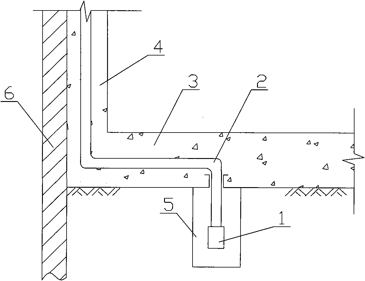
[0040] Such as image 3 As shown, when the building is supported by an underground diaphragm wall or cantilever piles, and one side of the inner wall of the underground concrete structure supports the formwork, the underground concrete side wall 4 is connected to the support structure 6, and the situation of the above-mentioned embodiment 1 is not applicable to this structure .

[0041] Firstly, the foundation pit is excavated, and the dewatering well 5 is set at the bottom of the foundation pit. A downwater pipe 2 is arranged in the dewatering well 5, and the lower port of the downwater pipe 2 is connected with the water pump 1, and the upper port of the downwater pipe 2 is led out along the concrete bottom plate 3 to be poured, and leads to the concrete to be poured integrally connected with the concrete bottom plate 3 The wall 4 extends upward along the interior of the concrete side wall 4, and extends to a place higher than the groundwater level. When leading out, the do...


PUM


Abstract

The invention discloses a closing method of a dewatering well in an underground structure, which is used for a dewatering well arranged at the bottom of the underground structure in a foundation pit. The method comprises the following steps of: arranging a dewatering pipe in the dewatering well, connecting the lower port of the dewatering pipe with a water pump, drawing out the upper port of the dewatering pipe from one side through the inside of a concrete base plate to be cast, moving the upper port of the dewatering pipe upwards along the foundation pit, and placing in a position higher than the underground water level; or drawing the upper port of the dewatering pipe through the inside of the concrete base plate to be cast, moving upwards with a concrete wall to be cast, which is connected with the concrete base plate into a whole, placing in a position higher than the underground water level, then starting a water pump to carry out dewatering operation, casting the concrete base plate and a side wall, stopping the dewatering operation after the concrete is set to a specified strength, and finally blocking the upper port of the dewatering pipe. The invention not only reduces the groundwater pressure at the closing part of the dewatering well, but also simplifies the closing process of the water drain pipe, thereby avoiding the water leakage of the structure as a result of the incorrect closing of the water drain pipe.

Description

technical field [0001] The invention relates to a construction method for keeping the underground foundation structure dry in the construction industry, in particular to a construction method for keeping the underground foundation structure dry by preventing and cutting off the underground water flow in the underground concrete structure. Background technique [0002] With the increase of high-rise buildings, there are more and more underground projects in construction, and the groundwater level of many construction sites is relatively high. In order to meet the construction requirements, well point precipitation is required on the construction site. In order to achieve precipitation, precipitation wells are usually arranged within the scope of the underground concrete structure, and the precipitation cannot be stopped before the construction of the underground structure is completed. After the construction of the bottom plate of the underground structure is completed, that ...

Claims


Application Information

Patent Timeline
IPC IPC(8): E02D19/20E02D19/10
Inventor 秦进
Owner TIANJIN 20 CONSTR
Why Eureka
Try Eureka