Industrial furnace door sealing device simple in operability

An industrial furnace and operational technology, which is applied in the field of sealing devices for industrial furnace doors, can solve problems such as insufficient temperature, insufficient sealing, and failure to ensure the sealing of the furnace body, and achieve the effect of increasing work efficiency and simple and convenient sealing operation

Pending Publication Date: 2022-01-04
NANJING VOCATIONAL UNIV OF IND TECH
View PDF1 Cites 0 Cited by
  • Summary
  • Abstract
  • Description
  • Claims
  • Application Information

AI Technical Summary

Problems solved by technology

[0003] After retrieval, Chinese Patent No. CN 210399995 U discloses a mechanical sealing device for industrial furnace kiln doors, which includes a main connecting rod, an upper lifting connecting rod, a lifting connecting rod adjusting sleeve and a lower lifting connecting rod, the main connecting rod There are two. The upper lifting link and the lower lifting link are connected with the lifting link adjustment sleeve through a screw to form a vertical link assembly. The position shaft is connected with one end of the main connecting rod, and forms a three-link moving structure, and two of the three-link moving structures are arranged symmetrically on the left and right sides of the furnace door; the middle part of the main connecting rod passes through the furnace The door

Method used


Image

  • Industrial furnace door sealing device simple in operability
  • Industrial furnace door sealing device simple in operability
  • Industrial furnace door sealing device simple in operability

Examples


Embodiment 1

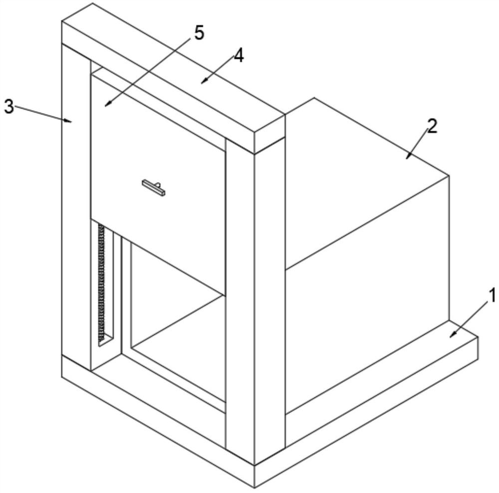
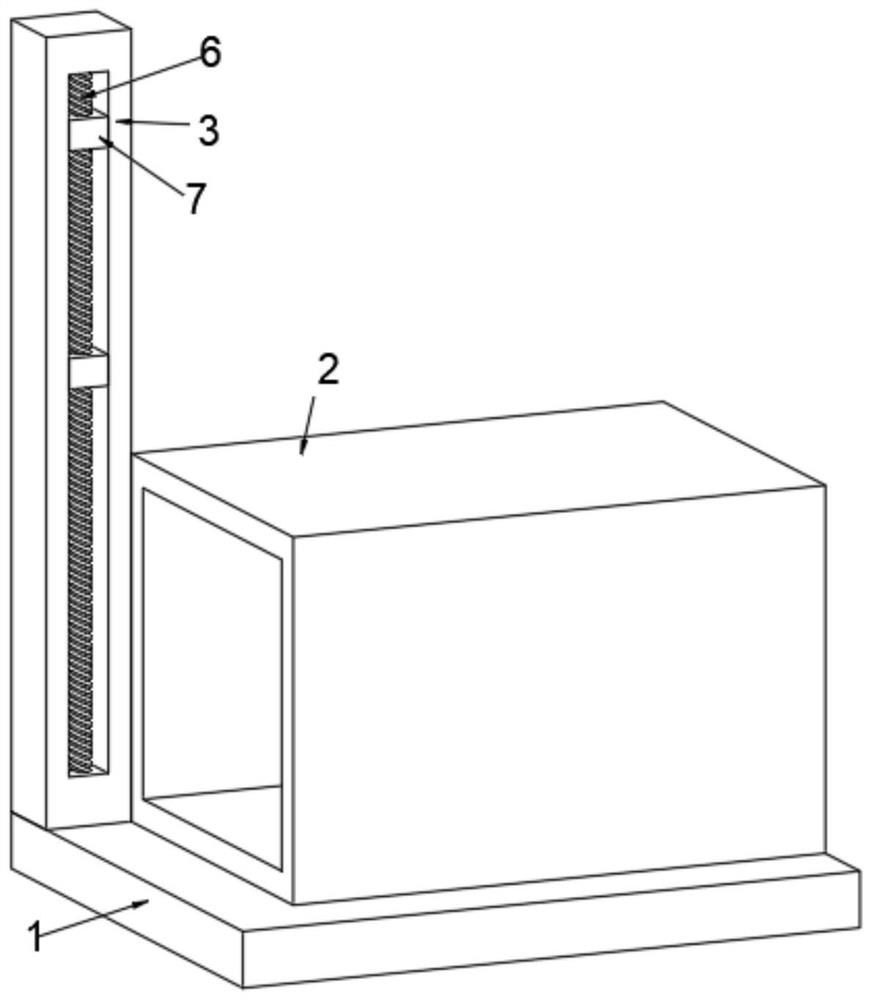
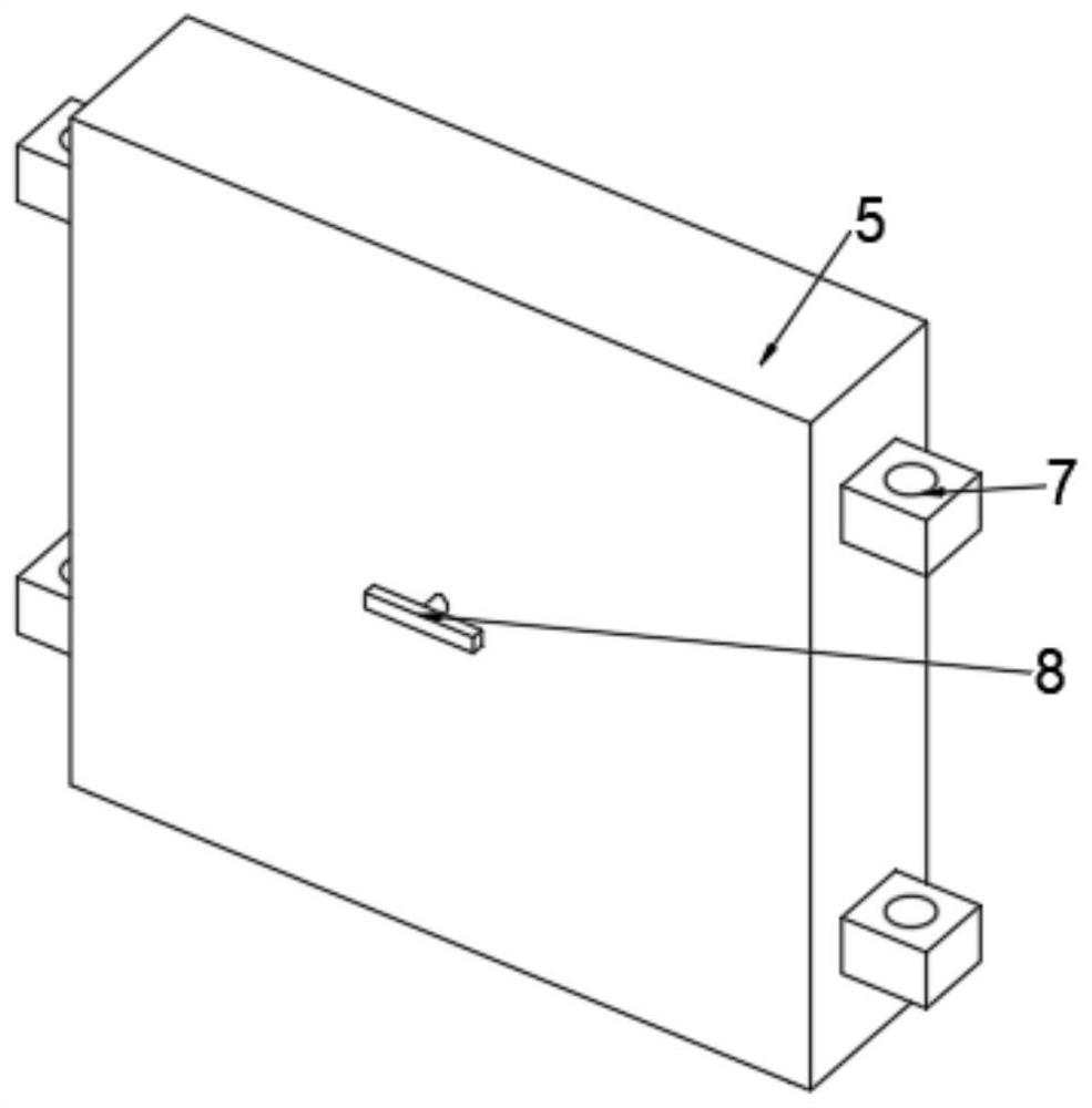
[0027] see Figure 1-Figure 6 , the present invention provides a technical solution: an industrial furnace door sealing device with simple operability, including a base 1, a furnace body 2 and a lifting column 3 are fixedly installed on the top of the base 1, and two adjacent lifting columns 3 The top of the lifting column 3 is fixedly installed with a top plate 4, and the inside of the lifting column 3 is movably installed with a first threaded rod 6, and the outer side of the first threaded rod 6 is threaded with a first moving block 7, and is fixed between two adjacent first moving blocks 7. Furnace door 5 is installed, and the back side of furnace door 5 is movably installed with heat insulation board 9, and the inside of furnace door 5 is provided with installation cavity, and the first partition plate 12, the second partition plate 13 and installation cavity are fixedly installed respectively in the installation cavity. plate 14, the mounting plate 14 is fixedly installe...

Embodiment 2

[0035] see Figure 4-Figure 5 , the present invention provides a technical solution: an industrial furnace door sealing device with simple operability, including a base 1, a furnace body 2 and a lifting column 3 are fixedly installed on the top of the base 1, and two adjacent lifting columns 3 The top of the lifting column 3 is fixedly installed with a top plate 4, and the inside of the lifting column 3 is movably installed with a first threaded rod 6, and the outer side of the first threaded rod 6 is threaded with a first moving block 7, and is fixed between two adjacent first moving blocks 7. Furnace door 5 is installed, and the back side of furnace door 5 is movably installed with heat insulation board 9, and the inside of furnace door 5 is provided with installation cavity, and the first partition plate 12, the second partition plate 13 and installation cavity are fixedly installed respectively in the installation cavity. plate 14, the mounting plate 14 is fixedly installe...


PUM


Abstract

The invention relates to the technical field of furnace door sealing devices and discloses an industrial furnace door sealing device simple in operability. The industrial furnace door sealing device simple in operability comprises a base, wherein a furnace body and lifting columns are fixedly mounted on the top end of the base, a top plate is fixedly mounted at the top ends of two adjacent lifting columns, first threaded rods are movably mounted in the lifting columns respectively, and a first moving block is in threaded connection to the outer side of each first threaded rod. By using the industrial furnace door sealing device simple in operability, when a third rotating rod rotates, a second threaded rod and a third threaded rod can be driven to rotate together, so that a second moving block and a third moving block can move oppositely; and when the second moving block and the third moving block move oppositely, a heat insulation plate can be driven to move through first pin shaft seats, connecting rods, moving frames and second pin shaft seats, and the moving frame are always movably mounted on the outer sides of corresponding pin shaft columns, so that the moving frames move towards one side of the heat insulation plate when moving, and in this way, the heat insulation plate can stretch into a furnace body to achieve the sealing effect.

Description

technical field [0001] The invention relates to the technical field of furnace door sealing devices, in particular to an industrial furnace door sealing device with simple operability. Background technique [0002] Industrial furnace is a kind of equipment manufactured and used by comprehensive application of materials science, combustion technology, heat transfer, thermodynamics, fluid mechanics, refractory materials, electrical engineering, material mechanics and other disciplines. The working system can be divided into two categories: one is the intermittent kiln, also known as the periodic kiln, which is characterized by the intermittent production of the kiln, and the temperature of the kiln changes in each heating cycle, such as the chamber kiln , trolley kiln, pit kiln, etc.; the second type is continuous kiln, which is characterized by continuous production of the kiln and the division of temperature zones in the kiln chamber. [0003] After retrieval, Chinese Paten...

Claims


Application Information

Patent Timeline
IPC IPC(8): F27D1/18F27D99/00
CPCF27D1/1858F27D99/0073
Inventor 满毅
Owner NANJING VOCATIONAL UNIV OF IND TECH
Why Eureka
Try Eureka