
Electric arc titanium pump and vacuum air pump group comprising same

An arc titanium pump and vacuum chamber technology, applied in the direction of pumps, mechanical equipment, machines/engines, etc., can solve the problem of reducing the pumping speed and pumping flow of the arc titanium pump, adsorbing gas molecules by a thin layer of active atoms, reducing pumping speed and pumping. Air flow and other issues, to achieve the effect of saving energy consumption, large pumping speed, and reducing cost of pumping

Inactive Publication Date: 2011-01-05
储继国
View PDF8 Cites 10 Cited by
  • Summary
  • Abstract
  • Description
  • Claims
  • Application Information

AI Technical Summary

Problems solved by technology

[0003] At lower pressure (≤5×10 -3 Pa) During operation, at the thicker film layer, the titanium atoms are covered by the subsequent evaporated titanium atoms without sufficient reaction, resulting in waste of titanium materials and increased operating costs
Operating at higher pressure, the thinner part of the titanium film cannot meet the pumping requirements, and the pumping speed is significantly reduced. The measured results show that: 5×10 -2 The pumping speed of Pa is only 5×10 -3 20% of Pa pumping speed, reduced pumping speed and pumping flow of arc titanium pump
[0004] In addition, the poor heat dissipation and temperature rise of the gas collection plate of the arc titanium pump in the prior art lead to a decrease in the probability of the thin layer of active atoms adsorbing gas molecules, which further reduces the pumping speed and pumping flow rate of the pump.

Method used


Image

  • Electric arc titanium pump and vacuum air pump group comprising same
  • Electric arc titanium pump and vacuum air pump group comprising same
  • Electric arc titanium pump and vacuum air pump group comprising same

Examples


Embodiment Construction

[0025] In order to make the object, technical solution and advantages of the present invention more clear, the present invention will be further described in detail below in conjunction with the accompanying drawings and embodiments. It should be understood that the specific embodiments described here are only used to explain the present invention, not to limit the present invention.

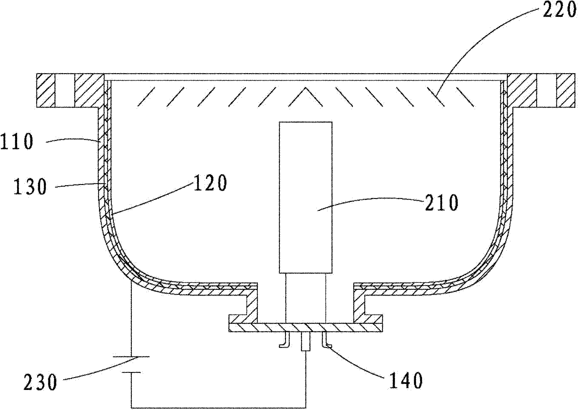
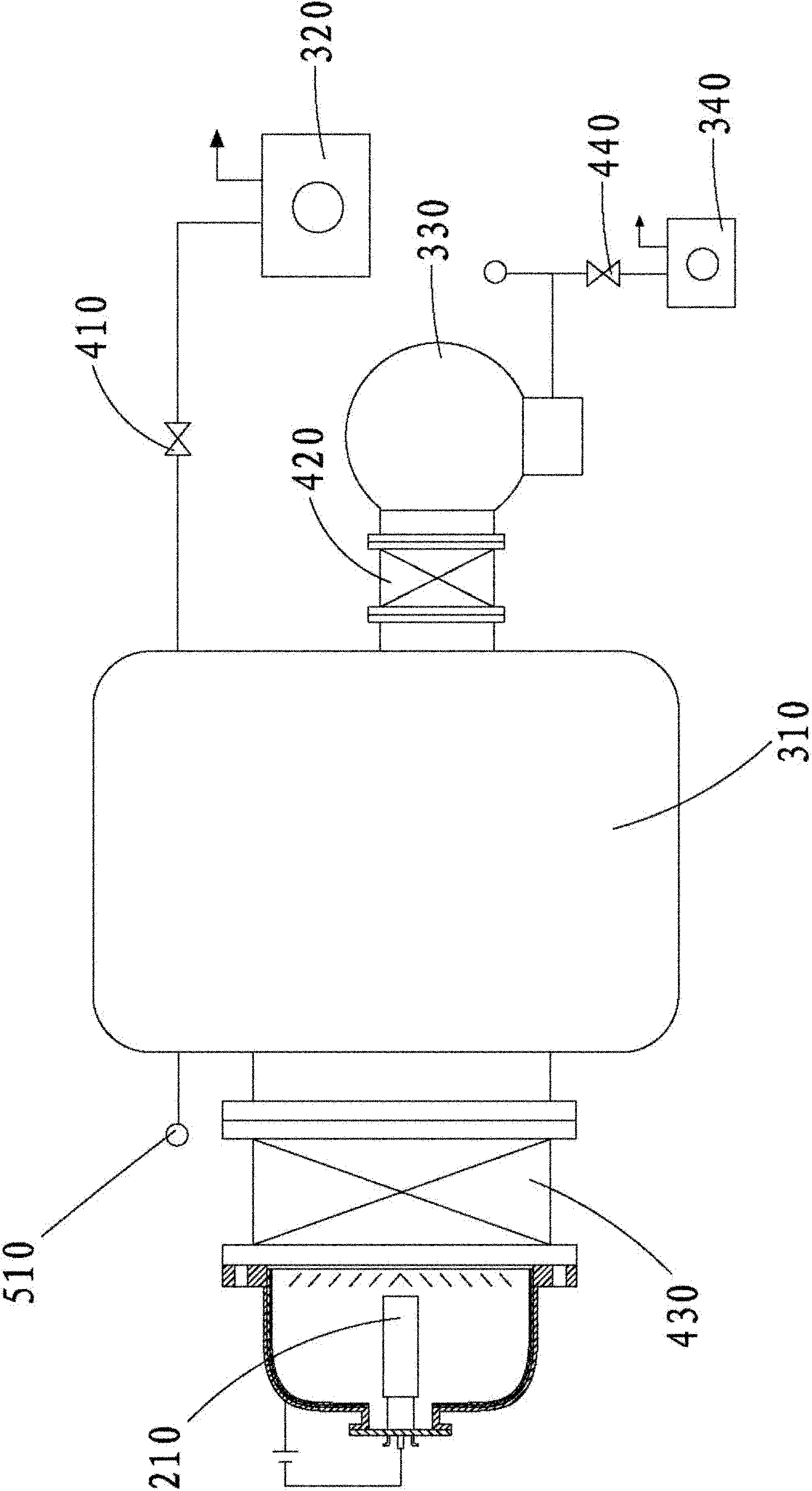
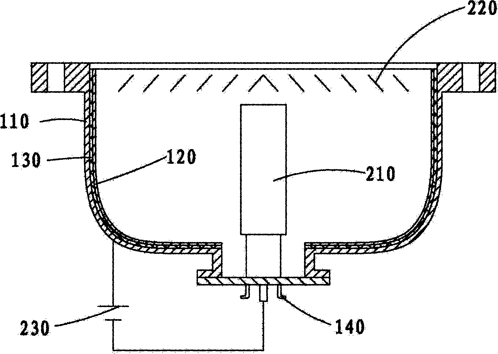
[0026] Such as figure 1 As shown, the embodiment of the present invention provides an arc titanium pump, including a pump casing 110, a collecting plate 120, a cathode arc source component 210, and a power supply 230, and the collecting plate 120 is arranged on the inner side wall of the pump casing 110, The cathode arc source component 210 is fixed in the pump casing 110; the cathode arc source component 210 includes a cathode target located on the outside and a magnetic component located inside the cathode target. The magnetic component can be an electromagnet or permanent magnet. The positi...


PUM


Abstract

The invention is applies to the technical field of vacuum acquisition and discloses an electric arc titanium pump and a vacuum air pumping group comprising the same. The electric arc titanium pump comprises a pump shell, a trapping plate, a cathode arc source member and a power supply, wherein the trapping plate is arranged on the inside wall of the pump shell, the cathode arc source member is fixedly arranged in the pump shell, and the pump shell and the cathode arc source member are in cylindrical shapes and are coaxially arranged; and the vacuum air pumping group comprises a vacuum chamber, wherein a molecular pump, a prepump, a roughing pump and the electric arc titanium pump are connected to the vacuum chamber. The electric arc titanium pump can be used for leading atoms steamed by the cathode arc source member to form an active film with even thickness and increasing the utilization rate of the cathode arc source member, thereby increasing pumping speed and air-pumping flow rate and reducing energy consumption and operation cost. The vacuum air pumping group can be used for replacing the current large-size diffusion pump with high energy consumption and high oil-vapor pollution and a Lobed pump air-pumping group in order to clean vacuum, save pumping energy consumption and reduce operation cost.

Description

technical field [0001] The invention belongs to the technical field of vacuum acquisition, and in particular relates to an arc titanium pump and a vacuum pumping unit comprising the arc titanium pump. Background technique [0002] At present, the arc titanium pump forms a thin layer of active atoms by evaporating the cathode target on the cathode arc source component to the collector plate, and the thin layer of active atoms reacts with gas molecules to achieve the pumping effect. In the prior art, the arc titanium pump adopts a planar cathode arc source structure, and the distance between the catch plate and the cathode arc source is uneven. In this way, the titanium film on the part near the catch plate to the cathode arc source is thicker, and the distance from the cathode arc source is relatively thick. The thinner titanium film on the farther part of the source member results in: [0003] At lower pressure (≤5×10 -3 Pa) During operation, at the thicker film layer, the...

Claims


Application Information

Patent Timeline
Patent Type & Authority Applications(China)
IPC IPC(8): F04B37/14
Inventor 储继国
Owner 储继国
Learn More