Combined PTFE oil seal with vent hole and manufacturing method and mounting method thereof
A kind of air vent and combined technology, which is applied in the direction of engine sealing, engine components, mechanical equipment, etc., and can solve problems such as inversion, tearing, increased holding force, bad influence of sealing body, rotating shaft and sealing medium, etc. , to achieve stable sealing effect and service life, avoid performance degradation, and avoid adverse effects
- Summary
- Abstract
- Description
- Claims
- Application Information
AI Technical Summary
Problems solved by technology
Method used
Image
Examples
Embodiment 1
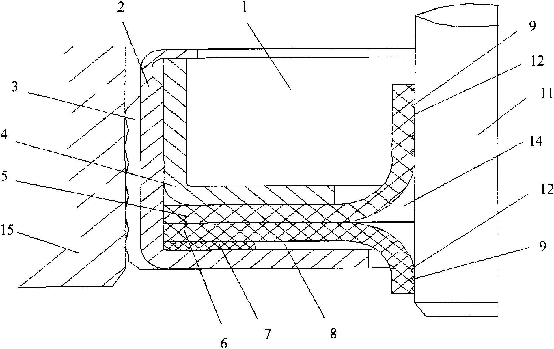
[0027] Such as figure 1 and figure 2 shown, where figure 1It is a structural schematic diagram of the original combined PTFE oil seal. The oil seal body 1 includes an outer skeleton 2, an outer elastic sealing body 3, an inner skeleton 4, a main PTFE sealing lip 5, a secondary PTFE sealing lip 6 and an elastic gasket 7; the main PTFE The sealing lip 5, the auxiliary PTFE sealing lip 6 and the rotating shaft 11 form a lip sealing belt 12 and a closed space 14; at the position of the lip sealing belt 12, the main PTFE sealing lip 5 and the auxiliary PTFE sealing lip 6 are provided with There are reflow lines9.
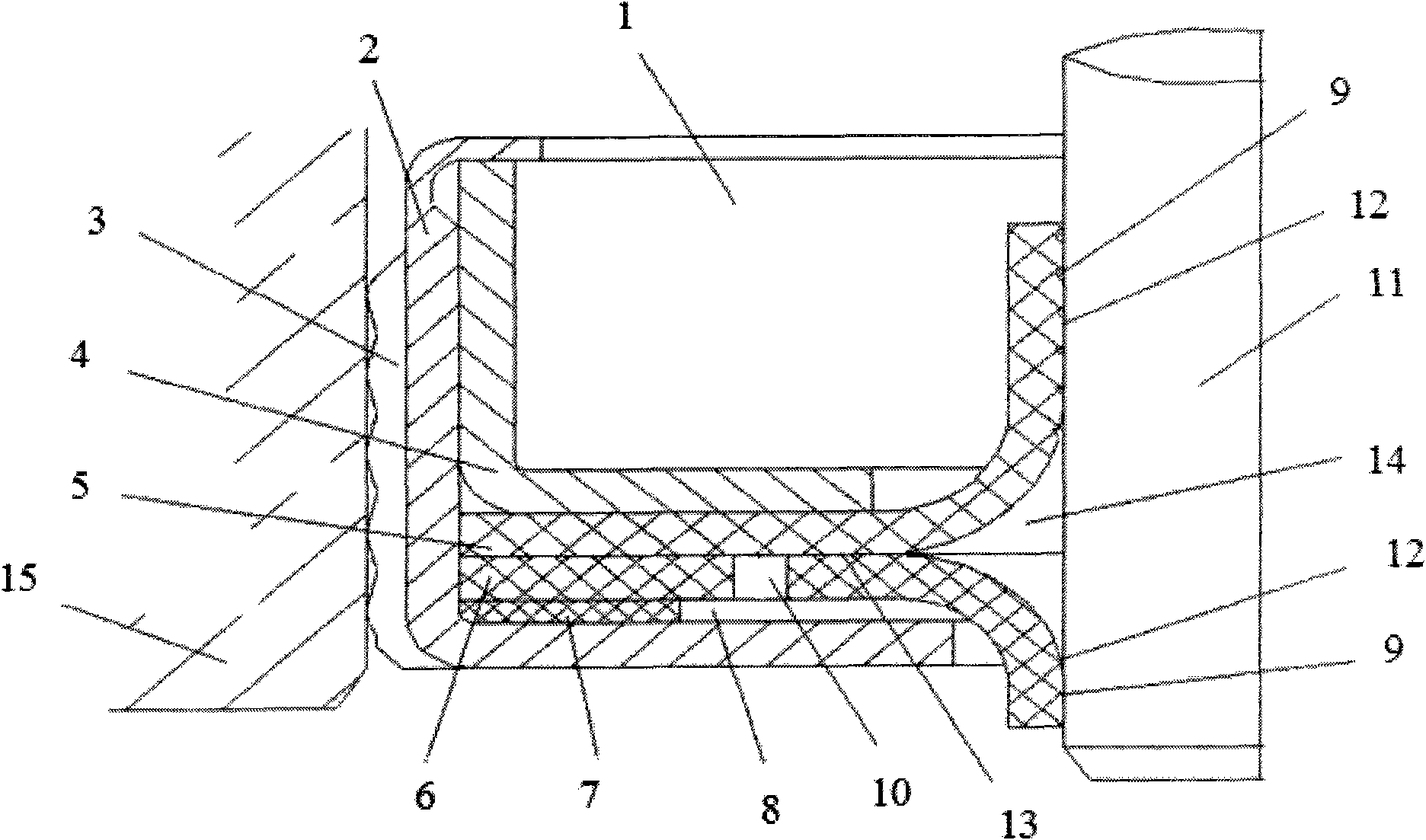
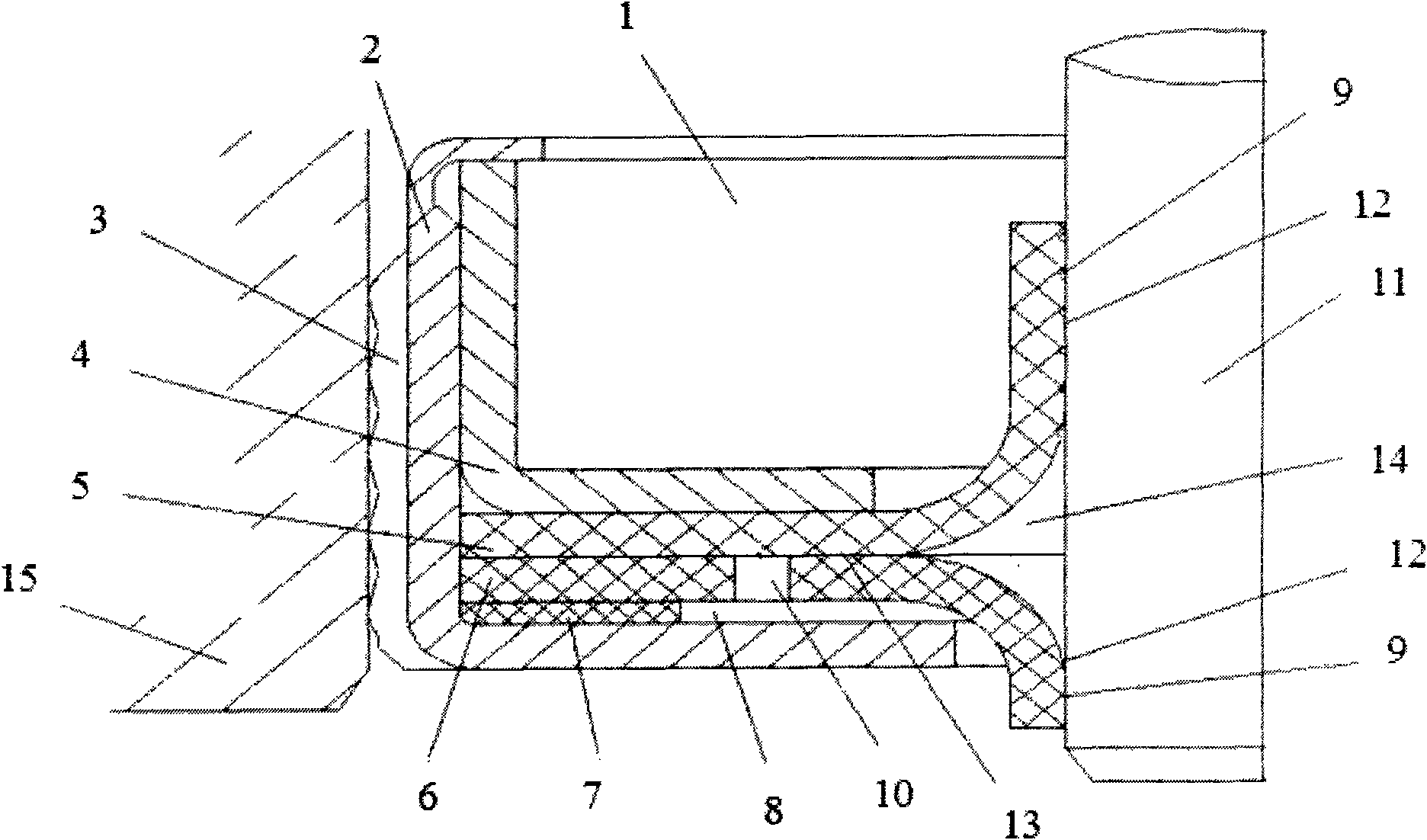
[0028] figure 2 It is a structural schematic diagram of a combined PTFE oil seal with a vent hole of the present invention, and its oil seal body 1 includes an outer skeleton 2, an outer elastic sealing body 3, an inner skeleton 4, a main PTFE sealing lip 5, and a secondary PTFE sealing lip 6 And the elastic sealing gasket 7, it is characterized in that: the auxili...
Embodiment 2
[0031] With embodiment 1, the difference is that the secondary PTFE sealing lip 6 is located on the lower surface and is exposed on the bottom gap 8 formed by the secondary PTFE sealing lip 6, the elastic gasket 7 and the outer skeleton 2 and the upper surface and the In the length space where the main PTFE sealing lip 5 is in close contact with, two elliptical vent holes 10 are provided at a position biased towards the inner hole of the elastic sealing gasket 7; at the position of the lip sealing strip 12, the main PTFE sealing lip 5 and the secondary PTFE sealing lip 6 are provided with two zigzag reflow lines 9 .
Embodiment 3
[0033] With embodiment 1, the difference is that the secondary PTFE sealing lip 6 is located on the lower surface and is exposed on the bottom gap 8 formed by the secondary PTFE sealing lip 6, the elastic gasket 7 and the outer skeleton 2 and the upper surface and the In the length space where the main PTFE sealing lip 5 closely contacts, a 2 mm circular vent hole 10 is provided at a position biased towards the inner hole of the elastic sealing gasket 7 .
PUM
 Abstract
Description
Claims
Application Information
 - R&D
- Intellectual Property
- Life Sciences
- Materials
- Tech Scout
- Unparalleled Data Quality
- Higher Quality Content
- 60% Fewer Hallucinations
Browse by: Latest US Patents, China's latest patents, Technical Efficacy Thesaurus, Application Domain, Technology Topic, Popular Technical Reports.
© 2025 PatSnap. All rights reserved.Legal|Privacy policy|Modern Slavery Act Transparency Statement|Sitemap|About US| Contact US: help@patsnap.com


