Gas nozzle for industrial kiln and distribution method using same

A gas burner and kiln technology, applied in the direction of combustion method, burner, combustion type, etc., can solve the problems of large excess air coefficient, short service life of burner, high gas consumption, etc., and achieve long flame, long service life, good rigidity

Inactive Publication Date: 2011-01-05
湖南金龙国际铜业有限公司
View PDF5 Cites 5 Cited by
  • Summary
  • Abstract
  • Description
  • Claims
  • Application Information

AI Technical Summary

Problems solved by technology

[0002] Gas burners used in industrial furnaces (including natural gas, coal gas, liquefied petroleum gas, etc.) generally consist of an outer tube and an inner tube, the outer tube is used for air intake, the inner tube is used for gas intake, and the outer tube has no air In the acceleration section, the inner pipe flame spraying adopts a direct spray structure, which causes the following defects: 1. High air consumption 2. The air is introduc

Method used


Image

  • Gas nozzle for industrial kiln and distribution method using same
  • Gas nozzle for industrial kiln and distribution method using same

Examples


Embodiment Construction

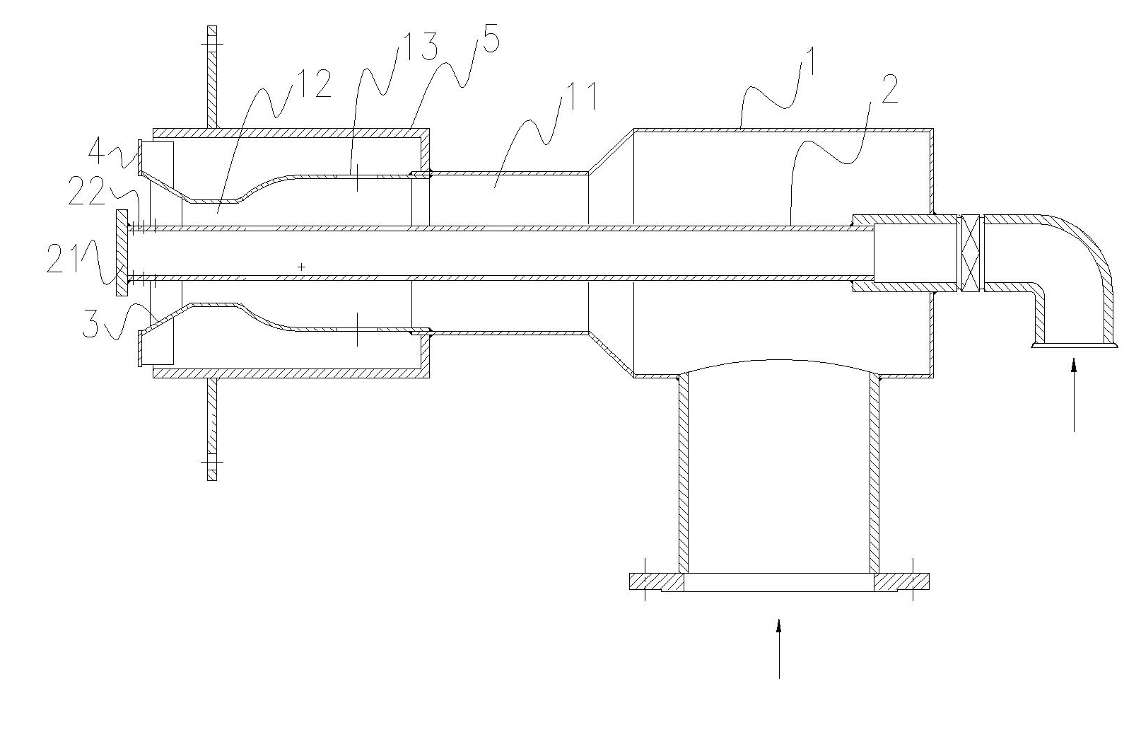
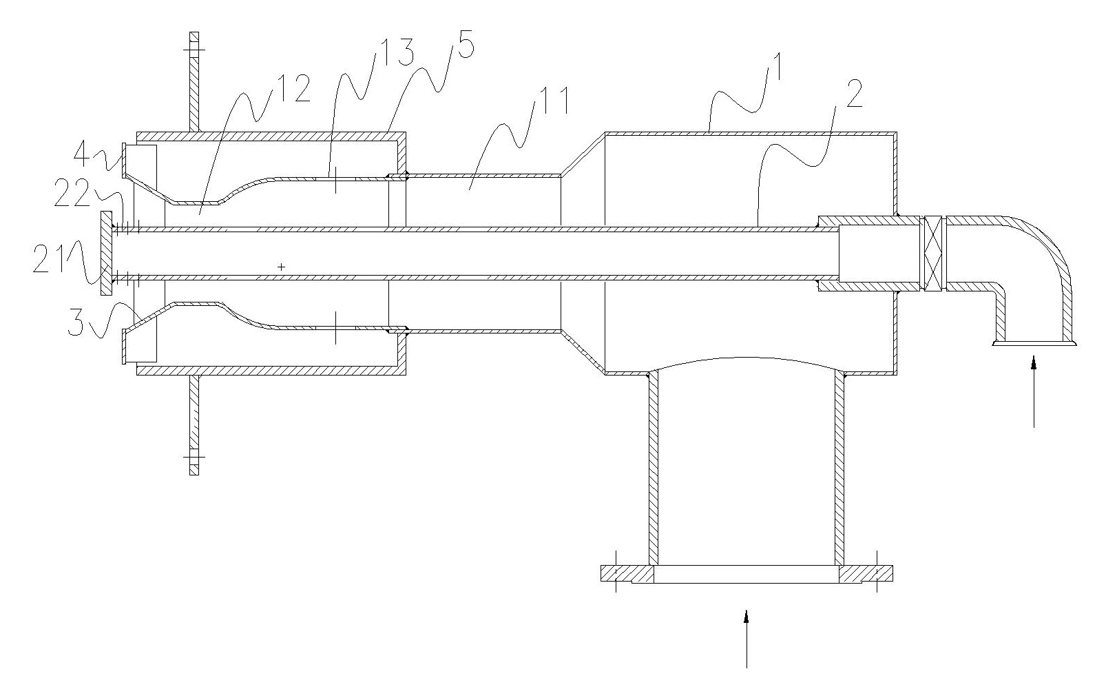
[0010] From figure 1 It can be seen that the gas burner used in the industrial kiln of the present invention comprises an outer tube 1 and an inner tube 2, the front end of the outer tube is provided with a bell mouth 3, the bell mouth has a burner lip 4, and the inner tube 2 runs through the outer tube 1, the outer tube 1 has at least two openings to form corresponding acceleration zones. In this embodiment, the outer tube 1 has two openings to form the first acceleration zone 11 and the second acceleration zone 12. The second acceleration zone The front end of 12 is that a bell mouth 3 is connected with burning lip limit 4. The front part of the inner pipe 2 is evenly distributed with gas outlets 21 (three in this embodiment) on the side wall, and a baffle 22 is provided on the end surface, so that the gas can reach the bell mouth 3 from the side gas outlets 21 and mix with air to form vortex. When the opening angle of the bell mouth 3 is 60°, it is most beneficial for the...


PUM


Abstract

The invention discloses a gas nozzle for an industrial kiln and a distribution method using the same. The gas nozzle for the industrial kiln comprises an air inlet outer tube and a gas inlet inner tube, wherein the outer tube is provided with at least two-stage closures to form at least two-stage accelerating regions; and the front part of the inner tube is provided with a gas outlet on the side face and a baffle plate on the end face, so that gas is mixed with air to form eddy. The distribution method using the gas nozzle comprises a step of mixing the gas and the air in a volume ratio of 1:9. The nozzle can make the gas well mixed in an eddy mixing state, achieves long flame and high rigidity, can make the gas fully combusted and has a stable gas excess air coefficient within 1.05; and compared with the conventional nozzle, the nozzle saves the gas by 30 to 50m<3>/ton and has long service life.

Description

technical field [0001] The invention relates to a gas burner used in an industrial kiln and a gas distribution method thereof. Background technique [0002] Gas burners used in industrial furnaces (including natural gas, coal gas, liquefied petroleum gas, etc.) generally consist of an outer tube and an inner tube, the outer tube is used for air intake, the inner tube is used for gas intake, and the outer tube has no air In the acceleration section, the inner tube fire injection adopts a direct injection structure, which causes the following defects: 1. High air consumption 2. The air is introduced at a certain speed at one time without acceleration, making the burning flame soft and short. 3. The structure of directly spraying flames makes the mixing of air and gas unsatisfactory, the excess air coefficient is large, and the fuel combustion is incomplete. 4. The front end of the burner is directly in contact with the high-temperature flame in the furnace, which is easy to b...

Claims


Application Information

Patent Timeline
IPC IPC(8): F23D14/22F23D14/46F23D14/78F23D14/60
Inventor 谭雄雅
Owner 湖南金龙国际铜业有限公司
Why Eureka
Try Eureka