
Limiting current oxygen sensor

A limiting current type, oxygen sensor technology, applied in the field of oxygen sensors, can solve problems such as composite ceramic cracking, deformed solid particles, sensor cracking, etc., and achieve strong oxygen measurement ability, good sealing, and prevent oxygen leakage.

Inactive Publication Date: 2011-01-05
NINGBO UNIV
View PDF3 Cites 7 Cited by
  • Summary
  • Abstract
  • Description
  • Claims
  • Application Information

AI Technical Summary

Problems solved by technology

[0002] The existing limiting current oxygen sensors can be divided into pore diffusion barrier type (including small pore diffusion barrier type, porous diffusion barrier type) and mixed conductor dense diffusion barrier type. For the pore diffusion barrier type oxygen sensor, in the long-term use process , due to the deformation of the pores in the diffusion barrier and the clogging of solid particles in the gas, the performance of this type of sensor will decline and fail.
The mixed conductor dense diffusion barrier oxygen sensor with a non-porous structure overcomes the above shortcomings, but because the sensitive body is a composite ceramic composed of a mixed conductor and a solid electrolyte with a laminated structure, the shrinkage rate of the two is inconsistent during the sintering process. It will lead to problems such as cracking, warping, and separation of the composite ceramics. Furthermore, due to the difference in thermal expansion coefficient between the two, the sensor will crack during use, reducing the tightness of the dense diffusion barrier layer and destroying the oxygen measuring ability of the oxygen sensor.

Method used


Image

  • Limiting current oxygen sensor
  • Limiting current oxygen sensor
  • Limiting current oxygen sensor

Examples


Embodiment Construction

[0012] The present invention will be further described in detail below in conjunction with the accompanying drawings and embodiments.

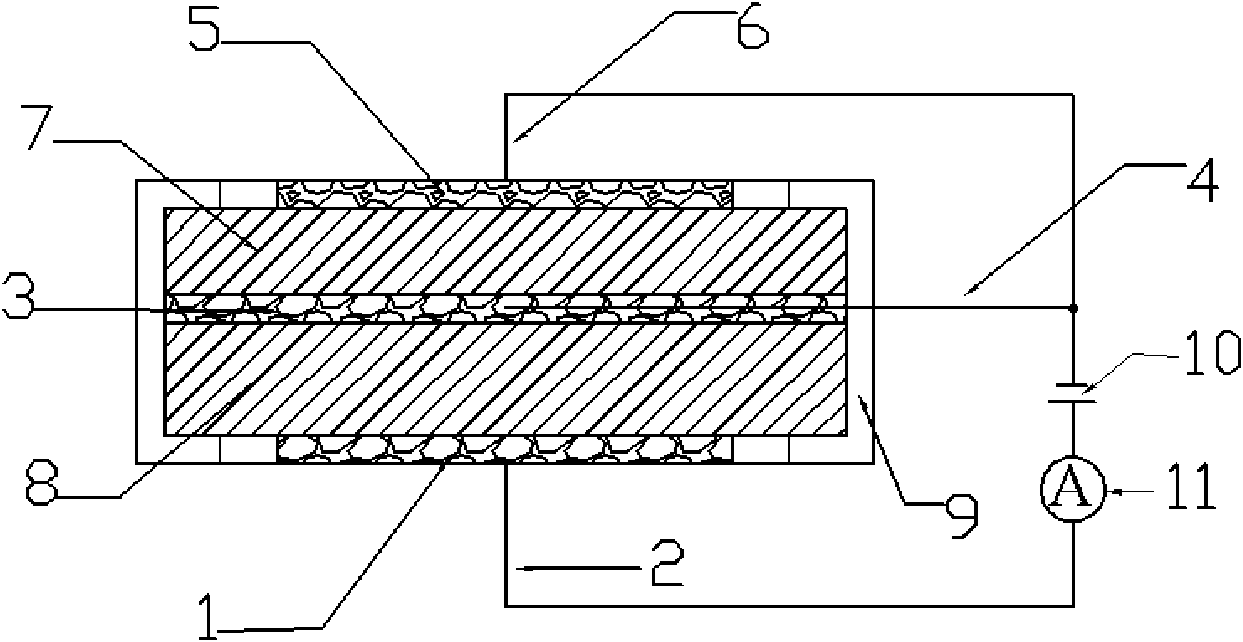
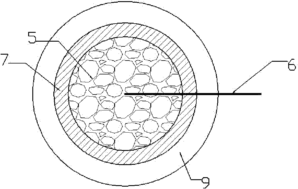
[0013] Such as figure 1 As shown in the figure, positive collector layer 1; positive collector layer lead 2; negative collector layer 3; negative collector layer lead 4; equipotential electrode layer 5; equipotential electrode layer lead 6; dense diffusion barrier layer 7; electrolyte layer 8; encapsulation layer 9; power supply 10; ammeter 11. The present invention is a limiting current type oxygen sensor using 8%mol yttrium stabilized zirconia (8YSZ) as the material of the dense diffusion barrier layer 7 and the solid electrolyte layer 8. It consists of an equipotential electrode layer 5, a dense diffusion barrier layer 7, a negative collector The electrode layer 3, the electrolyte layer 8, the positive collector layer 1 and the encapsulation layer 9 are composed, the positive collector layer 1 is arranged on the lower surface of the elect...


PUM


Abstract

The invention discloses a limiting current oxygen sensor, which comprises an electrolytic layer, a compact diffusion barrier layer, a positive collector layer and a negative collector layer, wherein the positive collector layer is arranged on the lower surface of the electrolytic layer. The limiting current oxygen sensor is characterized in that: the electrolytic layer and the compact diffusion barrier layer are made of the same material, namely zirconia-based ceramics or cerium oxide-based ceramics; the negative collector layer is arranged between the electrolytic layer and the compact diffusion barrier layer and is used for separating the electrolytic layer from the compact diffusion barrier layer; and an equipotential electrode layer is arranged on the upper surface of the compact diffusion barrier layer, and is connected with the negative collector layer through a lead. The limiting current oxygen sensor has the advantages of no problems of cracking, warping, separating and the like in the sintering process, difficult cracking in the process of using the sensor, good sealability of the compact diffusion barrier layer and strong oxygen measuring capacity of the oxygen sensor.

Description

technical field [0001] The invention relates to an oxygen sensor, in particular to a limiting current type oxygen sensor. Background technique [0002] The existing limiting current oxygen sensors can be divided into pore diffusion barrier type (including small pore diffusion barrier type, porous diffusion barrier type) and mixed conductor dense diffusion barrier type. For the pore diffusion barrier type oxygen sensor, in the long-term use process , due to the deformation of the pores in the diffusion barrier and the clogging of solid particles in the gas, the performance of this type of sensor will decline and fail. The mixed conductor dense diffusion barrier oxygen sensor with a non-porous structure overcomes the above shortcomings, but because the sensitive body is a composite ceramic composed of a mixed conductor and a solid electrolyte with a laminated structure, the shrinkage rate of the two is inconsistent during the sintering process. It will lead to problems such a...

Claims


Application Information

Patent Timeline
IPC IPC(8): G01N27/409
Inventor 邹杰简家文
Owner NINGBO UNIV
Learn More