
Monitoring system and method of arch dam

A monitoring system and technology for arch dams, applied in vibration measurement, measurement devices, vibration measurement in solids, etc., can solve the problems of arch dam safety hazards, inability to replace, noise interference, etc., to achieve convenient operation and management, low project cost, easy maintenance effect

Inactive Publication Date: 2011-01-05
TIANJIN UNIV
View PDF4 Cites 10 Cited by
  • Summary
  • Abstract
  • Description
  • Claims
  • Application Information

AI Technical Summary

Problems solved by technology

The above-mentioned monitoring is basically static or quasi-static monitoring. For the stability of the dam abutment and the overall displacement of the dam body, the static method is still applicable. It is difficult to grasp the instantaneous change of the working state of the arch dam and the evolution process over time, and the arch dam's instantaneous arching failure and the arching failure caused by the cumulative effect of cracks will threaten the safe operation of the arch dam
In addition, since the current sensors are generally pre-embedded into the dam body during the construction period of the arch dam, long-term operation will cause the sensor to fail and cannot be replaced, and the effective monitoring of the dam body will be lost. Can not be accurately grasped, causing safety hazards in the operation of the arch dam
Moreover, the sensors currently used are generally acceleration sensors, which are used to realize the identification and health diagnosis of the arch dam state. In practical applications, the low-frequency noise interference of the frequency spectrum obtained by using the acceleration sensor is relatively serious, while the vibration of the arch dam The frequency band is mainly in the low frequency band, so it is impossible to get more accurate results by using the acceleration sensor

Method used


Image

  • Monitoring system and method of arch dam
  • Monitoring system and method of arch dam
  • Monitoring system and method of arch dam

Examples


Embodiment Construction

[0026] In order to make the object, technical solution and advantages of the present invention clearer, the implementation manner of the present invention will be further described in detail below in conjunction with the accompanying drawings.

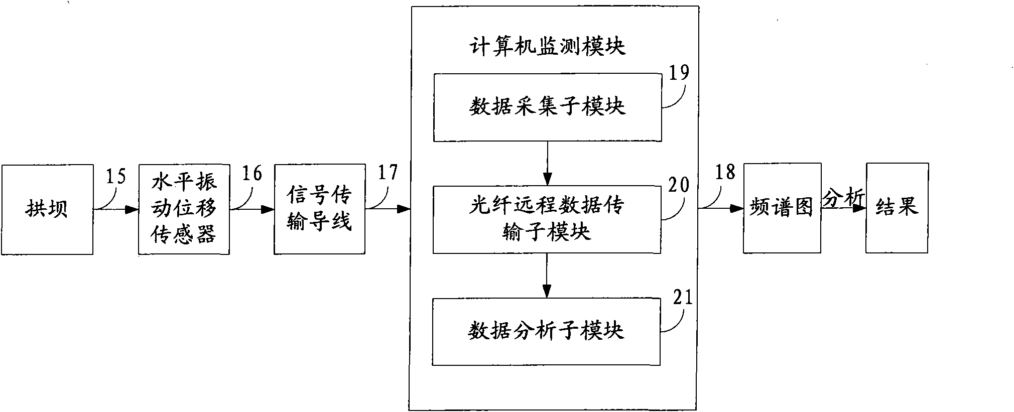
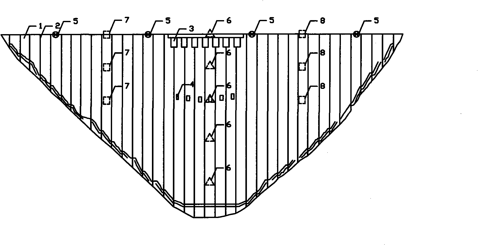
[0027] In order to monitor the various working states of the arch dam, discover the possible damage of the arch dam in time, and quickly find out the damage location, an embodiment of the present invention provides an arch dam monitoring system, see figure 1 and figure 2 , see the description below:

[0028] The arch dam monitoring system includes: an arch dam 15, a horizontal vibration displacement sensor 16, a signal transmission wire 17 and a computer monitoring module 18, wherein the arch dam 15 includes: an arch dam section 1, a construction transverse joint 2, a surface hole 3, a middle Hole 4, top arch 5, arch crown beam 6, 1 / 4 top arch axis position beam 7 and 3 / 4 top arch axis position beam 8, the horizontal vibration displa...


PUM


Abstract

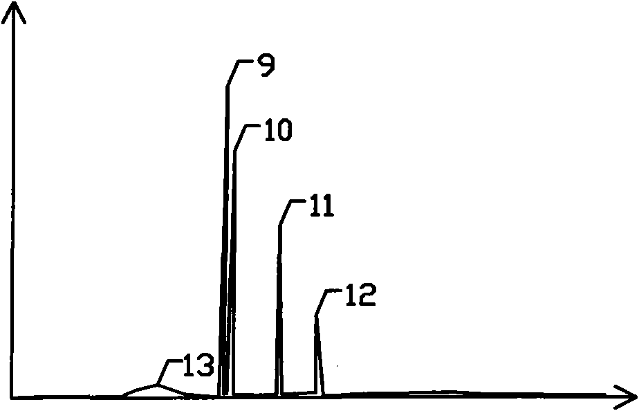
The invention discloses monitoring system and method of an arch dam, relating to the technical field of automatic monitoring of sluicing building structures in hydraulic and hydropower engineering. In the invention, a horizontal vibration displacement sensor is arranged on the arch dam; various working states of the arch dam can be monitored by analyzing a frequency spectrogram; the damage of the arch dam, which is possible to generate, is found in time; and the position of the damage is fast found so as to be convenient to repair and strengthen by adopting various engineering measures. The monitoring system has the advantages of simple form, convenient construction, easy maintenance, low engineering construction cost and convenient operation and management and can realize the remote control during operation. The invention reduces the interference by using the horizontal vibration displacement sensor, enhances the monitoring accuracy and meets the requirements of practical application.

Description

technical field [0001] The invention relates to the technical field of automatic monitoring of drainage building structures in water conservancy and hydropower projects, in particular to an arch dam monitoring system and a monitoring method. Background technique [0002] The discharge structures of high-head and large-flow water conservancy projects mostly adopt the arch dam form, which belongs to the high-order hyperstatically indeterminate structure of the space shell, and its stability mainly depends on the overall arch-shaped force state of the dam body, and the force is transmitted through the action of the arch to both sides. [0003] At present, the monitoring of arch dams mainly includes deformation monitoring, seepage and seepage pressure monitoring, stress and strain monitoring, gap opening and closing degree monitoring, and temperature monitoring. The above-mentioned monitoring is basically static or quasi-static monitoring. For the stability of the dam abutment ...

Claims


Application Information

Patent Timeline
IPC IPC(8): G01N29/12G01H1/00
Inventor 刘昉李成业
Owner TIANJIN UNIV
Learn More