
Dry etching method

A dry etching and etching technology, used in electrical components, semiconductor/solid-state device manufacturing, circuits, etc., can solve problems such as damage to the device structure and unsatisfactory cleaning effect, and achieve the reduction of particle residues, particle residues, and damage. Effect

Inactive Publication Date: 2011-01-05
SEMICON MFG INT (SHANGHAI) CORP
View PDF1 Cites 8 Cited by
  • Summary
  • Abstract
  • Description
  • Claims
  • Application Information

AI Technical Summary

Problems solved by technology

[0006] The present invention solves the problem that the cleaning effect after dry etching in the prior art is not ideal and will damage the formed device structure

Method used


Image

  • Dry etching method
  • Dry etching method
  • Dry etching method

Examples


Embodiment approach

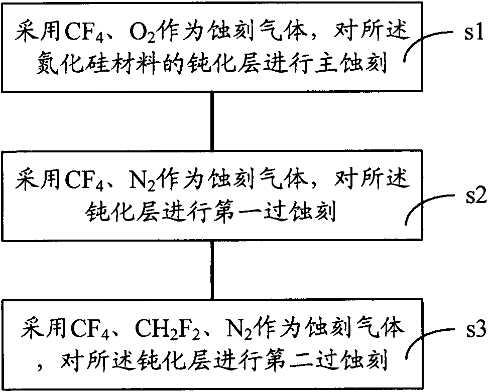
[0016] Based on this, the dry etching method of the present invention achieves the purpose of reducing particle residues by improving the etching process and reducing the damage of the etching gas of the dry etching to the exposed non-etching materials under the premise of meeting the etching requirements. According to an embodiment of the method of dry etching of the present invention, it comprises:

[0017] The main etching and overetching are performed sequentially on the material layer to be etched, wherein the etching gas used in the overetching includes at least a gas that can increase the amount of polymer produced in the etching reaction.

[0018] In the above embodiment, by using a gas that can increase the amount of polymer generated in the etching reaction in the overetching, more polymers are generated in the etching reaction, so that the polymer forms a protective layer on the surface of the non-etching material exposed by etching , reducing the damage of the etch...


PUM


Abstract

The invention relates to a dry etching method comprising the step of sequentially carrying out primary etching and over etching to a material layer to be etched, wherein etching gas adopted during the over etching at least comprises gas for increasing the generation quantity of a polymer in etching reaction. The dry etching method is beneficial to reducing the damage of the etching as to non-etching materials, thereby reducing particle residuals generated by the damage. Correspondingly, due to the reduction of the particle residuals, the cleaning time after dry etching can be shortened, thereby the damage of a cleaning solution to the formed device structure is reduced.

Description

technical field [0001] The invention relates to the field of semiconductor manufacturing, in particular to a dry etching method. Background technique [0002] The cleaning process after dry etching is a very important step in the semiconductor manufacturing process. In this cleaning process, the cleaning solution must be able to effectively remove residues (such as photoresist particles or other particles generated by etching), and must not damage the formed device structures, such as aluminum wires, via holes, and dielectrics. layers etc. [0003] The traditional cleaning process after dry etching mostly uses an organic solvent mixture containing hydroxylamine (HA, hydroxylamine) and phosphodiphenol (Catechol) as a cleaning solution. Such products generally have the disadvantages of high pollution, high toxicity and expensive treatment costs. [0004] For this reason, various new cleaning solutions have been developed in the industry. For example, US Pat. No. 6,517,738 B...

Claims


Application Information

Patent Timeline
Patent Type & Authority Applications(China)
IPC IPC(8): H01L21/00H01L21/3213H01L21/3065H01L21/311C23F4/00
Inventor 张海洋孙武符雅丽
Owner SEMICON MFG INT (SHANGHAI) CORP
Learn More