Permanent-magnet synchronous motor adopting concentrated winding

A permanent magnet synchronous motor, centralized technology, applied in the direction of synchronous motors with stationary armature and rotating magnets, synchronous machine parts, magnetic circuit rotating parts, etc., can solve the problem of electromagnetic power and electromagnetic rotation of permanent magnet synchronous motors Small torque, difficulty in off-line of distributed windings, long ends of distributed windings, etc., to achieve high electromagnetic power and electromagnetic torque, weaken armature reaction, and light weight

Inactive Publication Date: 2011-01-05
SHANGHAI DIANJI UNIV
View PDF0 Cites 1 Cited by
  • Summary
  • Abstract
  • Description
  • Claims
  • Application Information

AI Technical Summary

Problems solved by technology

[0004] In the traditional permanent magnet synchronous motor, the permanent magnet synchronous motor with the rotor shown in Figure 1 (a), (b), (c) has a large weight and a large moment of inertia, and the direct axis of the permanent magnet synchronous motor rotor The reactance and the quadrature axis reactance are equal, and its essence is the sedentary pole motor. The electromagnetic power and electromagnetic torque of the common permanent magnet synchronous motor are small; the direct axis reactance and AC of the permanent magnet synchronous motor with the rotor shown in Fig. The shaft reactance is not equal, it belongs to the salient pole motor, and it also has high electromagnetic power. However, in order to make the air gap flux closer to the sinusoidal distribution, the stator needs to use distributed windings. The use of distributed windings has the following disadvantages: (1) The ends of distributed windings are long and waste a lot of copper (2) The leakage reactance of distributed windings is large (3) It is difficult to offline and the structure of distributed windings is complex

Method used


Image

  • Permanent-magnet synchronous motor adopting concentrated winding
  • Permanent-magnet synchronous motor adopting concentrated winding
  • Permanent-magnet synchronous motor adopting concentrated winding

Examples


Embodiment Construction

[0027] The specific embodiments of the present invention will be explained in detail below in conjunction with the drawings.

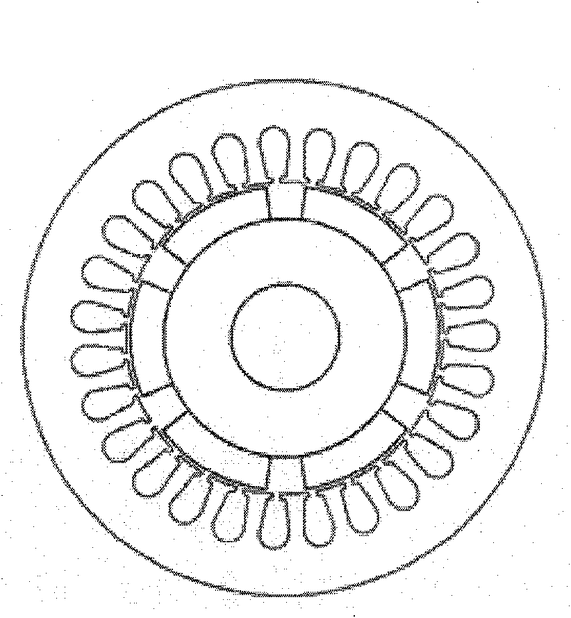
[0028] Reference attachment figure 2 , The present invention uses a concentrated winding permanent magnet synchronous motor, including a stator 10 and a rotor 20, there is an air gap 30 between the stator 10 and the rotor 20, the stator 10 includes a stator core 11 and a stator winding 12, the rotor 20 includes a rotor The iron core 21, the rotating shaft 22, and the permanent magnet steel 23, the stator winding 12 is a concentrated winding, the rotor 20 is an eccentric rotor, and the air gap 30 between the stator 10 and the rotor 20 is non-uniform air Gap. The permanent magnetic steel 23 is a radial magnetic steel.

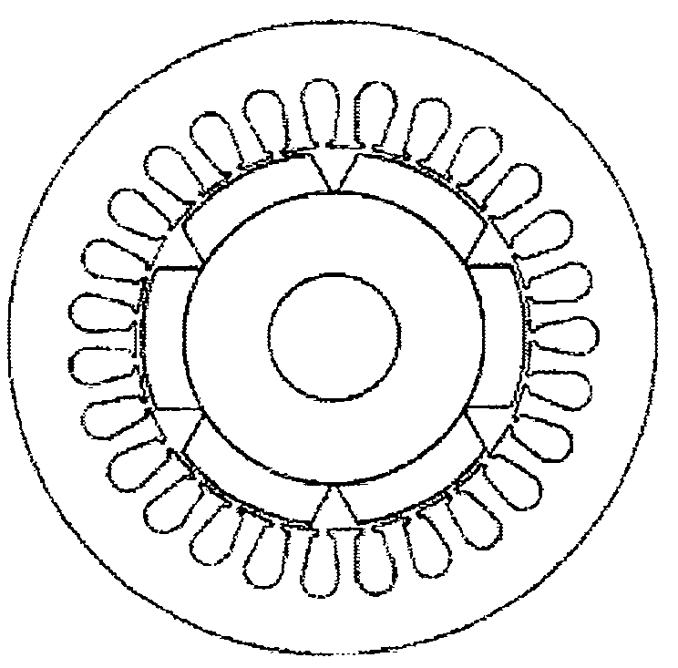
[0029] Reference attachment image 3 The center of the rotor 20 of the present invention deviates from the center of the stator 10. As shown in the figure, the center 0 of the stator 10 does not coincide with the center 0'of the arc formed by...


PUM


Abstract

The invention provides a permanent-magnet synchronous motor adopting a concentrated winding, comprising a stator and a rotor. An air gap is formed between the stator and the rotor, the stator comprises a stator core and a stator winding, and the rotor comprises a rotor core, a rotating shaft and a permanent-magnet steel magnet. The permanent-magnet synchronous motor is characterized in that that stator winding is an integrated winding, the rotor is an eccentric rotor, and the air gap between the stator and the rotor is an uneven air gap. The invention has the advantages of less materials consumption, simple structure, convenient production and light weight, reduces the additional loss of motor energy and improves the utilization rate of the motor energy.

Description

Technical field [0001] The invention relates to an AC synchronous motor, in particular to a permanent magnet synchronous motor adopting concentrated winding. Background technique [0002] The air gap between the stator and the rotor of the traditional permanent magnet synchronous motor is uniform, and the stator winding adopts distributed winding to make the air gap magnetic flux of the motor closer to the sinusoidal distribution. [0003] The permanent magnet rotor commonly used in traditional permanent magnet synchronous motors has roughly five shapes, as shown in Figure 1. The permanent magnets shown in Figure 1 (a), (b), and (c) are magnetized in a radial direction. The permanent magnets are attached to the surface of the rotor. The direct-axis reactance and quadrature-axis reactance of the rotor are equal, similar to a hidden pole motor Figure 1(d) shows that although the permanent magnet is magnetized radially, the permanent magnet is located inside the rotor. Between the ou...

Claims


Application Information

Patent Timeline
Patent Type & Authority Applications(China)
IPC IPC(8): H02K21/12H02K21/02H02K1/27
Inventor 邵士良赵朝会常守亮袁龙生张迪严晓霞李全峰
Owner SHANGHAI DIANJI UNIV
Why Eureka
Try Eureka