Link state delivery method and device of packet transport network

A packet transport network and link state technology, applied in transmission systems, digital transmission systems, data exchange networks, etc., can solve problems such as deadlocks, inconsistent states, and ineffective triggering of signal failure packets, and achieve deadlock solutions. , the effect of improving reliability

Inactive Publication Date: 2011-01-05
ZTE CORP
View PDF4 Cites 10 Cited by
  • Summary
  • Abstract
  • Description
  • Claims
  • Application Information

AI Technical Summary

Problems solved by technology

[0007] The inventors have found that the existing LST mechanism has at least the following problems: because the PE cannot distinguish whether the disconnection of the UNI port at the local end is caused by the local end or the remote end, it is easy for the two ends to continuously send CSF messages to each other, thus Cause deadlock; when the CE-PE links at both ends are disconnected at the same time, the signal failure message cannot be effectively triggered, and the failure status of one end cannot be transmitted to the other end, resulting in the problem of inconsistent status; Some LST mechanisms can only transmit CE-PE client layer failure signals, but PE-PE failure signals cannot be transmitted

Method used


Image

  • Link state delivery method and device of packet transport network
  • Link state delivery method and device of packet transport network
  • Link state delivery method and device of packet transport network

Examples


Embodiment 1

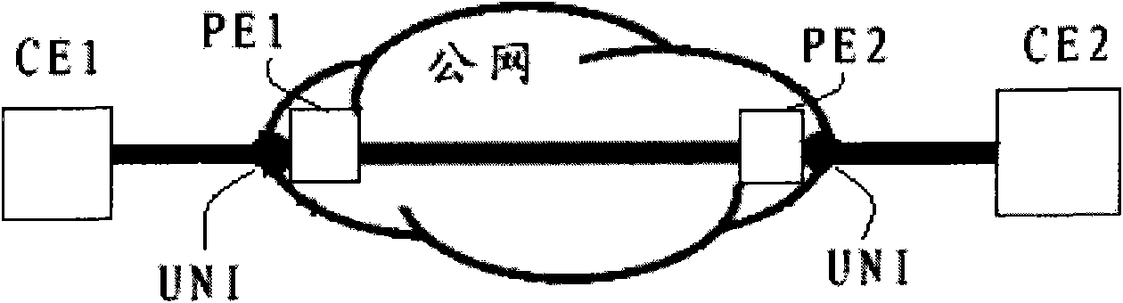
[0070] Such as Figure 8 As shown, this embodiment describes the CE1-PE1 service port signal state detection and management.

[0071] When a CE1-PE1 link fault occurs, perform the following steps:

[0072] In step S802, it is judged whether it is detected that the CE1-PE1 link is down for the first time, and if yes, step S804 is executed.

[0073] In step S804, it is further judged whether the UNI physical port is set with the remote link identification bit. If it is set, it means that the CE1-PE1 link down is the transmission of the remote link status, and returns directly without processing to prevent deadlock.

[0074] Step S806, if the remote identification bit is empty, further judge whether the public network client layer is in the SF state, and if the client layer fails, return without processing.

[0075] In step S808, when the down of the UNI port is neither caused by the remote link nor the public network, but the link of CE1-PE1 itself is abnormal, a CSF message i...

Embodiment 2

[0080] Such as Figure 9 As shown, this embodiment describes the client service state management of the remote PE2.

[0081] When receiving the CE1-PE1 link defect notification sent by PE1, perform the following steps:

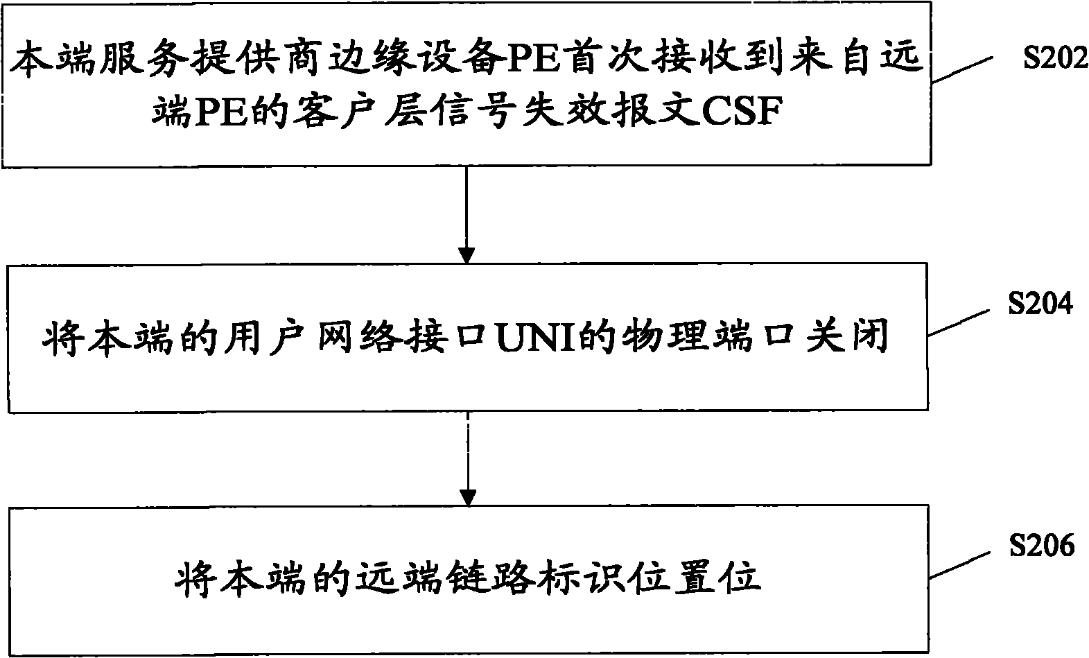
[0082] Step S902, judging whether the CSF message sent by PE1 is received for the first time.

[0083] In step S904, if the CSF message is received for the first time, it means that the remote CE1-PE1 link is down, and the UNI physical port of the local end is set to the remote identification bit.

[0084] Step S906, judge whether the UNI physical port of CE2-PE2 is down, if the port of CE2-PE2 is down, do not process, and return.

[0085] Step S908, if the UNI physical port of CE2-PE2 is up, then close the UNI physical port, and the user equipment CE2 can perceive that the remote user equipment CE1 is unreachable.

[0086] When receiving the CE1-PE1 link defect disappearance notification sent by PE1, perform the following steps:

[0087] Step S910, judging ...

Embodiment 3

[0093] Such as Figure 10 As shown, this embodiment describes signal detection at the client layer of PE1-PE2 on the public network.

[0094] The detection of part of the client layer signal on the public network can be deployed on the service layer, including the tunnel and link layer. At this time, it is necessary to record the binding relationship between the service layer tunnel or the link layer and the client layer to propagate the failure signal; it can also be deployed On the client layer PW. You can choose according to different needs.

[0095] Step S1002, whether the network manager wants the OAM message to work at the service layer, needs to pay attention to the status of the service layer and the client layer at the same time.

[0096] Step S1004, if yes, configure the OAM detection message to work in the service layer, configure the predetermined expiration time, etc., and enable the propagation function, when the service layer detects the failure, it can propag...


PUM


Abstract

The invention discloses a link state delivery method and a device of a packet transport network. The method comprises the following steps: a home-terminal service provider edge PE receives a client layer signal failure message (CSF) from a far end PE for the first time; the physical port of the home-terminal user network interface (UNI) is closed; the far-end link of a home terminal indicates a position site, wherein the far-end link indication site is used for indicating that the link state from a far-end CE to the far-end PE is disconnected. The invention discloses a link state delivery device of a packet transport network. In the invention, the far-end link indication site is additionally arranged on a UNI physical port and is used for recording that the disconnection of the UNI physical port of a CE-PE link is caused by the home terminal or the far end; and when the UNI physical port disconnection is caused by home terminal or the far end, the signal failure message is not triggered to the far end so as to avoid the phenomenon that two ends continuously send the signal failure message, solve the problem of deadlock and improve system reliability.

Description

technical field [0001] The present invention relates to the field of PTN (Packet Transport Network, packet transport network), in particular, to a link state transfer method and device of a packet transport network. Background technique [0002] T-MPLS (Transport Multi-Protocol Label Switching, Transport Multi-Protocol Label Switching) is one of the main packet transmission technologies. T-MPLS has strong OAM (Operation Administration and Maintenance, operation, management and maintenance) capabilities. G8113 Defined by G8114, it provides alarm management, performance management and other management tools. [0003] The PTN network business model is: on the user side, the physical real port is bound to UNI (Usernetwork interface, user network interface), and UNI is bound to CIP (CustomerInstance Port, customer instance port); on the public network side, PW (Pseudo Wire, Pseudowire) and tunnel (tunnel) are bound into VIP (Virtual Instance Port, virtual instance port); CIP and...

Claims


Application Information

Patent Timeline
Patent Type & Authority Applications(China)
IPC IPC(8): H04L12/56H04L12/70
Inventor 郭瑞芳
Owner ZTE CORP
Why Eureka
Try Eureka