
Cleaning tank

A technology for cleaning tanks and tank bodies, applied in the field of cleaning tanks, can solve the problems of reduced strip production efficiency, increased strip production costs, damage to cleaning tank spray pipes and nozzles, etc., to reduce production costs and improve strip production Efficiency, the effect of preventing stacking of steel

Inactive Publication Date: 2012-06-06
QUANYOU METALLURGICAL EQUIP TECH DEV
View PDF0 Cites 0 Cited by
  • Summary
  • Abstract
  • Description
  • Claims
  • Application Information

AI Technical Summary

Problems solved by technology

Therefore, the cleaning tank in the prior art is prone to strip steel stacking, and then damages the tank body, spray pipe and nozzle of the cleaning tank, thereby causing the need to stop the strip production for maintenance, so that the strip production efficiency is greatly reduced, and production is stopped. Repairs also lead to increased strip production costs

Method used


Image

  • Cleaning tank
  • Cleaning tank
  • Cleaning tank

Examples


Embodiment Construction

[0021] The present invention will be further described in conjunction with accompanying drawing:

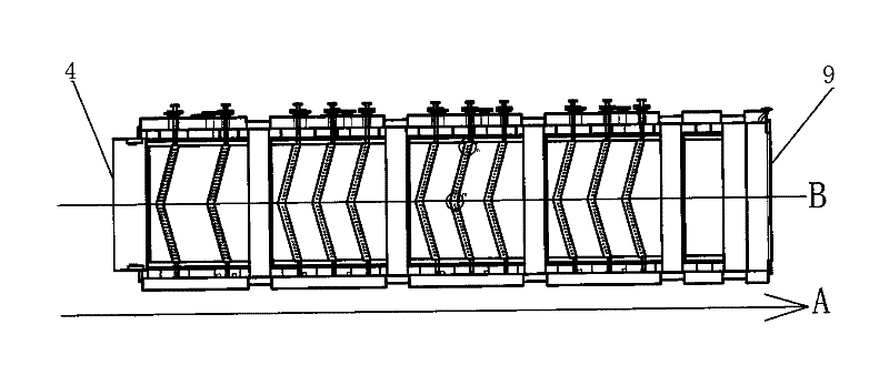
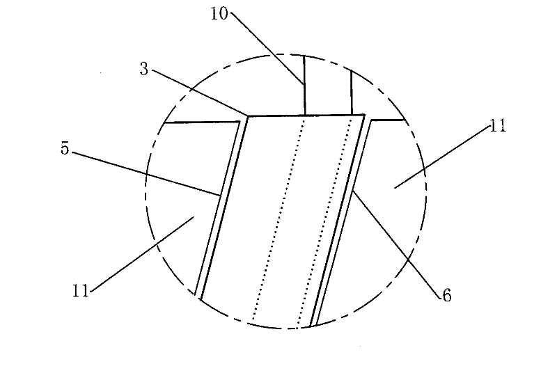
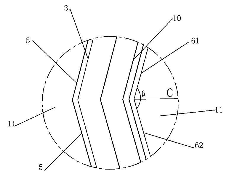
[0022] like Figure 1 to Figure 5 As shown, the cleaning tank of this embodiment includes a tank body 1 and a tank cover 2 that seals the tank body 1, and the adjoining part of the tank body 1 and the tank cover 2 is sealed with water. When steam is passed inside, the leakage of steam can be effectively reduced; a strip steel guide plate 11 is installed in the tank body 1, and the strip steel guide plate 11 includes an upper guide plate 7 and a lower guide plate 8, and the upper guide plate 11 Form strip channel between guide plate 7 and described lower guide plate 8; And the distance between described upper guide plate 7 and described lower guide plate 8 is 50 millimeters, the thickness that is suitable for strip steel is 1.8 millimeters-4 mm; along the moving direction A of the strip: the adjoining sides of the two adjacent upper guide plates 7 are respectively the head side 5...


PUM


Abstract

The invention discloses a cleaning tank, which comprises a tank body. Strip steel guide plates are arranged in the tank body; along the strip steel moving direction A, the adjacent edges of the adjacent two strip steel guide plates are a head side edge close to a strip steel inlet and a tail side edge far from the strip steel inlet respectively; and the included angle between at least one sectionof the tail side edge and the strip steel moving direction A is not equal to 90 degrees. The cleaning tank can effectively prevent the strip steels from being piled, reduce the production cost of thestrip steels and improve the production efficiency of the strip steels.

Description

technical field [0001] The invention relates to strip steel cleaning equipment after strip steel pickling in the field of strip steel production, in particular to a cleaning tank used for strip steel cleaning and effectively preventing stacking of steel. Background technique [0002] In the field of strip steel production, it is necessary to clean the residual acid liquid and debris on the surface of the strip steel after pickling, usually by transporting the strip steel to a cleaning tank for cleaning. In the cleaning tank of the prior art, there is a gap between adjacent guide plates, and a spray pipe is arranged in the gap to spray water to the strip for cleaning through the nozzles on the spray pipe. Along the moving direction of the strip: Since the boundary line between adjacent strip steel guide plates is perpendicular to the moving direction of the strip steel, the head of the strip steel often collides with the edge of the strip steel guide plate at the boundary lin...

Claims


Application Information

Patent Timeline
Patent Type & Authority Patents(China)
IPC IPC(8): B08B3/02
Inventor 曹楠
Owner QUANYOU METALLURGICAL EQUIP TECH DEV
Learn More