Design method of wind-proof anti-theft weight restraint bracket

A design method and anti-theft technology, applied in the field of machinery, can solve the problems of high frictional resistance, sticking of falling weights, hidden dangers of driving safety, etc., and achieve the effect of good fixing effect, reduced frictional resistance and ensuring driving safety.

Inactive Publication Date: 2011-01-12
周建科
View PDF0 Cites 0 Cited by
  • Summary
  • Abstract
  • Description
  • Claims
  • Application Information

AI Technical Summary

Problems solved by technology

[0002] At present, the anchor compensation device in the electrified railway catenary system uses a single hoop, a single restriction conduit and a single conduit adjustment plate for the weight restriction frame used to restrict the movement of the weight string. Therefore, in the strong wind area, the weight string can swing back and forth around

Method used


Image

  • Design method of wind-proof anti-theft weight restraint bracket
  • Design method of wind-proof anti-theft weight restraint bracket
  • Design method of wind-proof anti-theft weight restraint bracket

Examples


Embodiment 1

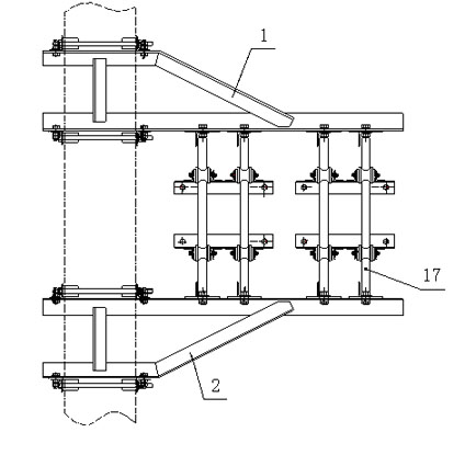
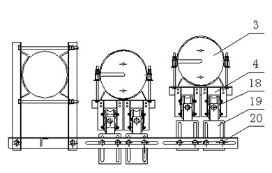
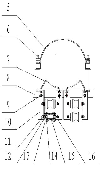
[0017] like figure 1 , image 3 As shown, the upper and lower ends of the drop mass string 3 are fixed on the upper and lower two drop mass fixing frames 4, and one end of the falling mass fixing frame 4 is the dropping mass fixing frame hoop 5, and the other end is the dropping mass fixing frame body 8 , the "M" type hoop 7 is welded on the body 8 of the drop mass fixing frame, and the two ends of the dropping mass fixing frame hoop 5 are fixed on both ends of the body 8 of the dropping mass fixing frame through M16 connecting bolts 6; One end is fixed between the "M"-shaped hoop 7 and the drop mass fixing frame hoop 5 .

[0018] like figure 2 As shown, two groups of parallel guide wheel connection angles 10 are vertically fixed on the body 8 of the drop weight fixing frame through M12 connecting bolts 9, and two parallel guide wheel connection angles 10 in each group are vertically connected with two parallel Guide pulley 15, a gap of 5 mm is formed between the two guide...

Embodiment 2

[0023] This embodiment is basically the same as Embodiment 1. The difference is that this embodiment uses one weight string 3. Therefore, the windproof and anti-theft type weight restraining frame of this embodiment includes a restraining frame bracket 1 and a set of weights. The mass fixing frame 4, a set of restricting conduits 17, a set of conduit regulating plates 19 and connecting pieces.

[0024] The described set of drop-weight fixing frames 4 includes two upper and lower drop-weight fixing frames 4, the two sets of restricting conduits 17 include two restricting conduits 17, and the described set of conduit adjusting plates 19 includes four conduit adjusting plates. 19.

[0025] The sizes of the bolts and nuts in the above embodiment are not limited to the sizes in the embodiments, they can also be adjusted according to the actual size of the weight string 3; the gap formed between the two guide pulleys 15 is not only It is limited to 5mm in the embodiment, and can al...


PUM


Abstract

The invention relates to a weight restraint bracket, in particular to a design method of a wind-proof anti-theft weight restraint bracket. The invention is characterized in that the weight restraint bracket comprises guide pulleys, one end of a weight fixing frame is provided with an anchor ear of the weight fixing frame, the other end thereof is the body of the weight fixing frame, the M-shaped anchor ear is welded on the body of the weight fixing frame, and both ends of the anchor ear of the weight fixing frame are fixed at both ends of the body of the weight fixing frame by bolts; and two groups of parallel guide pulley angle cleats are vertically fixed on the body of the weight fixing frame by bolts, two parallel guide pulleys are vertically connected between the two parallel guide pulley angle cleats of each group, and a gap is formed between the two guide pulleys. The weight restraint bracket of the invention overcomes the problems of oscillation, impact, clamping stagnation, deflection and the like of the weight restraint bracket in a strong wind area, and simultaneously changes the sliding friction between the anchor ear of the weight and the restraint pipe into rolling friction, thereby reducing the friction resistance.

Description

technical field [0001] The invention relates to a weight limiting frame, in particular to a design method of a windproof and anti-theft weight limiting frame, belonging to the technical field of machinery. Background technique [0002] At present, the anchor compensation device in the electrified railway catenary system uses a single hoop, a single restriction conduit and a single conduit adjustment plate for the weight restriction frame used to restrict the movement of the weight string. Therefore, in the strong wind area, the weight string can swing back and forth around the restriction conduit , collide with each other, and even cause the string of weights to get stuck and deflected, and intrude into the limit to bring hidden dangers to driving safety. There is sliding friction between the hoop of the weight and the restricting conduit, and the frictional resistance is relatively large when the string of the weight moves. Contents of the invention [0003] The purpose ...

Claims


Application Information

Patent Timeline
IPC IPC(8): B60M1/26B61B12/00
Inventor 周建科
Owner 周建科
Why Eureka
Try Eureka