Lithium ion polymer battery pack assembling structure and assembling method
A technology for assembling structures and battery packs, which is applied in the direction of isolation of battery pack parts, structural parts, batteries and their environment, etc., can solve the problems of battery pack deformation, battery unusability, etc., to prolong life, facilitate replacement, and avoid external vibration Effect
- Summary
- Abstract
- Description
- Claims
- Application Information
AI Technical Summary
Problems solved by technology
Method used
Image

Examples
Embodiment 1
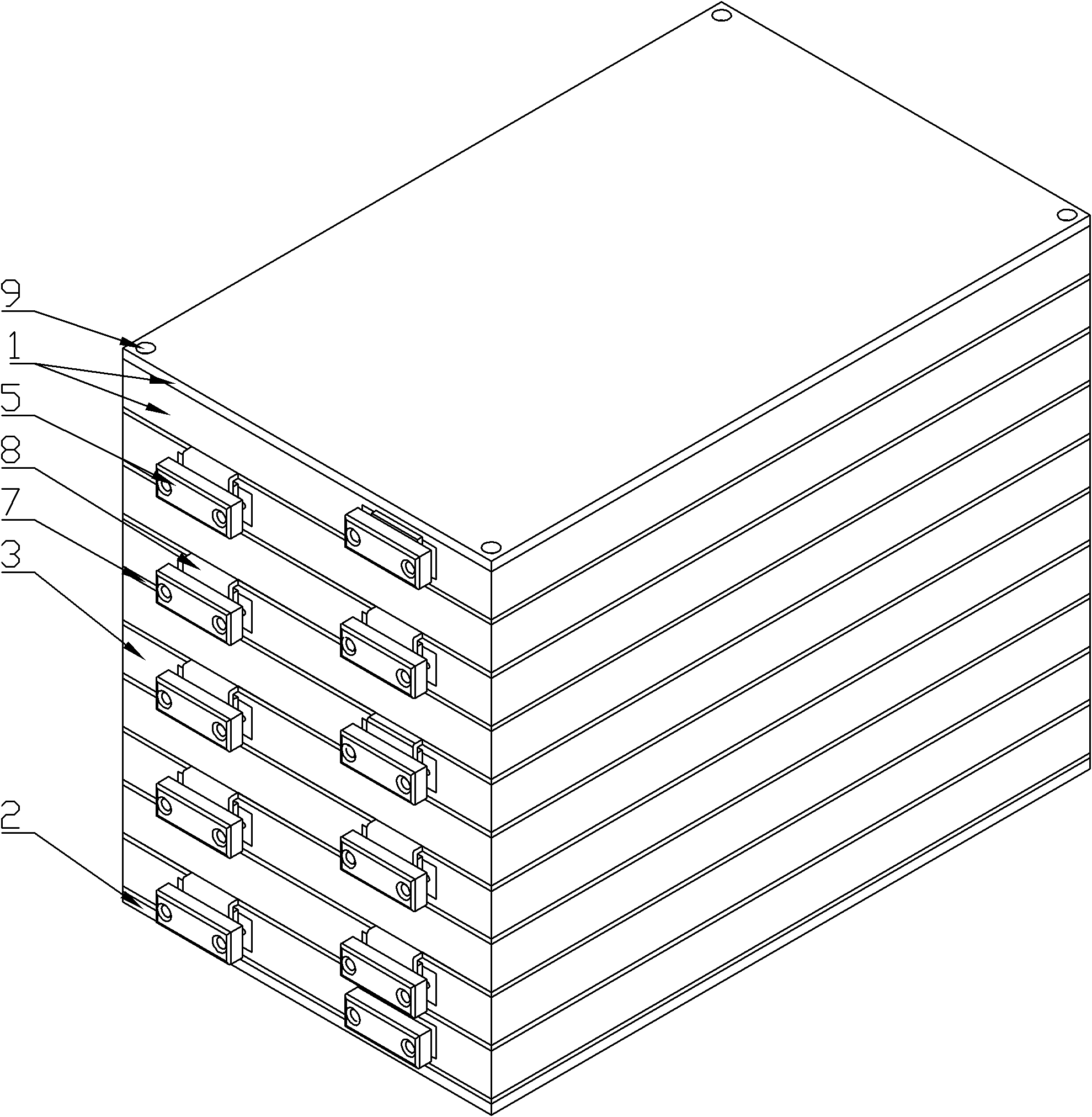
[0032] Such as figure 1 , 2 , 3, the battery pack assembly structure includes an upper cover 1, a lower cover 2, N batteries and N-1 assembly frames 3 between them. The battery includes a battery tank 6 and a battery fixing part 7; the battery tank 6 is rectangular, and the battery tank 6 extends outward to form a battery fixing part 7, and the positive and negative pole ears 8 provided on the battery tank 6 protrude from the fixing part 7, as shown in the above figure The battery shown is a single-side electrode battery, and the positive and negative pole tabs 8 of the single-side electrode battery are located on the same side, and the adjacent batteries are separated by the assembly frame 3. Rectangular battery containing cavity, battery containing cavity periphery is assembling frame 3 frame parts, and battery containing cavity matches with battery groove 6 and makes battery groove 6 extend in the battery containing cavity, and frame part matches with battery fixing part 7...
Embodiment 2
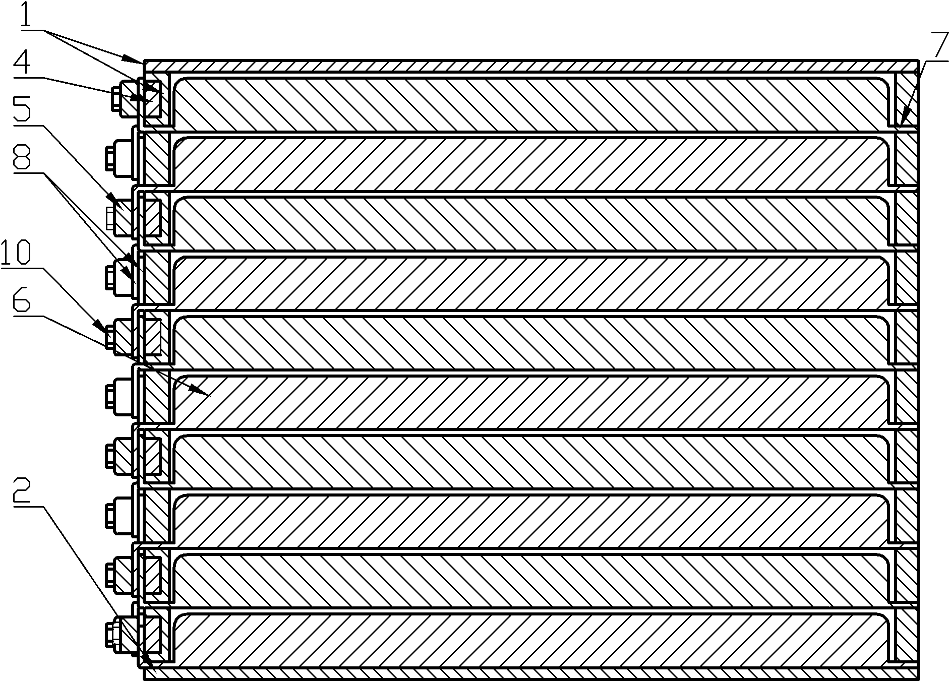
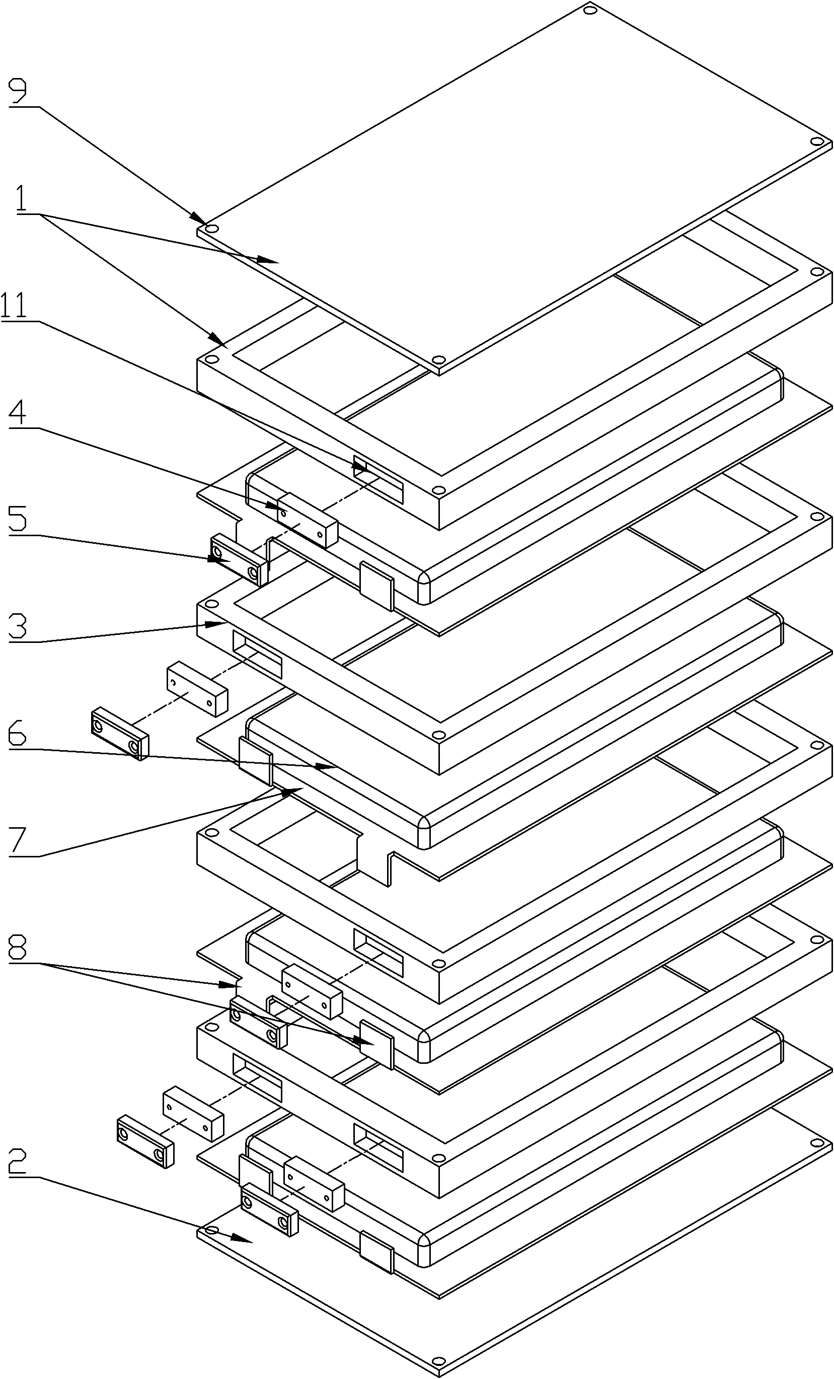
[0044] Such as Figure 4 , 5 , 6, and 7, the battery is a double-side electrode battery, and the positive and negative pole ears 8 of the single-side electrode battery are separately arranged on both sides of the battery, and the corresponding installation grooves 11 are located on both sides, and the positive pole ears 8 of the battery are bent upwards to meet the The negative electrode of the previous battery is overlapped, and the tab 8 on the other side is bent downward to overlap the positive electrode of the next battery, and the installation slots 11 on the assembly frame 3 on the same side are arranged at intervals.
[0045] If the battery is a single-slot battery, such as Figure 5 As shown, the battery fixing portion 7 is located at the lower end of the battery slot 6 ; the upper surface of the lower cover 2 is flat to abut against the battery fixing portion 7 .
[0046] If the battery is a dual-slot battery, such as Figure 6 , 7 As shown, the battery fixing par...
PUM
 Abstract
Description
Claims
Application Information