Gas insulated switchgear

A gas-insulated opening and closing and insulation technology, which is applied in the direction of switchgear, switchgear setting, electric switch, etc., can solve the problems of troublesome construction, difficult construction, and difficult bending of copper pipes, etc.

Inactive Publication Date: 2011-01-12
KK TOSHIBA
View PDF3 Cites 2 Cited by
  • Summary
  • Abstract
  • Description
  • Claims
  • Application Information

AI Technical Summary

Problems solved by technology

[0005] In addition, the conventional copper pipe is suitable for the straight part of the pipe, but the copper pipe itself is difficult to bend, so when it is used for the bent part of the pipe, special jigs or tools are required. Difficulty setting up the construction site
In this regar

Method used


Image

  • Gas insulated switchgear
  • Gas insulated switchgear
  • Gas insulated switchgear

Examples


no. 1 example

[0015] [Configuration of the first embodiment]

[0016] Below, according to figure 1 , Figure 2A as well as Figure 2B The first embodiment of the present invention will be specifically described.

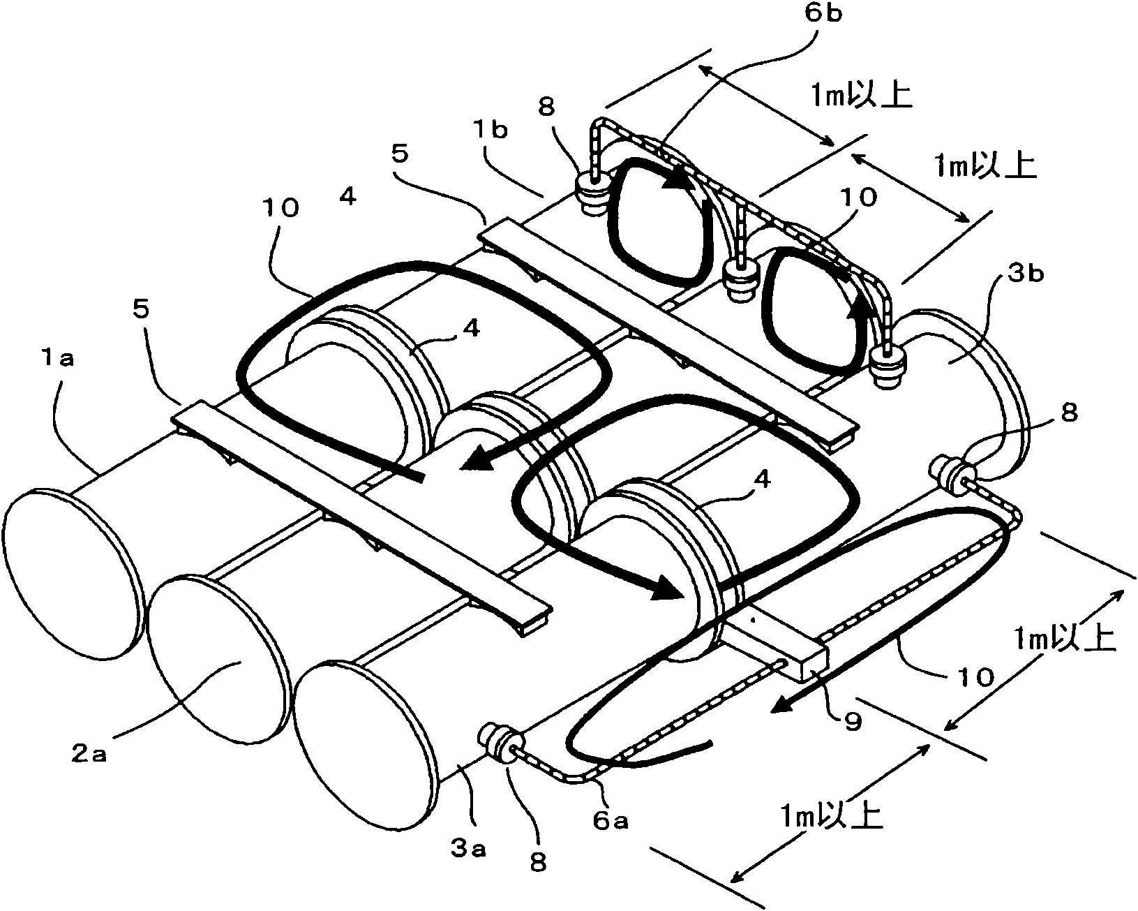
[0017] figure 1 It is a perspective view which shows the position example of the gas piping arrange|positioned between adjacent airtight containers. In the figure, reference numerals 1a, 1b, 2a, 2b, 3a, and 3b denote three-phase airtight containers in which conductors or electrically connected devices are housed, respectively. SF is enclosed in airtight containers 1a, 1b, 2a, 2b, 3a, 3b 6 Gas and other insulating gases. The airtight containers 1 a and 1 b , 2 a and 2 b , and 3 a and 3 b are connected by flanges 4 . The airtight containers of the respective phases are divided by gas at the flange portion 4 as the boundary portion thereof, and direct gas movement does not occur between adjacent airtight containers of the same phase.

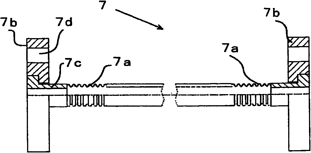
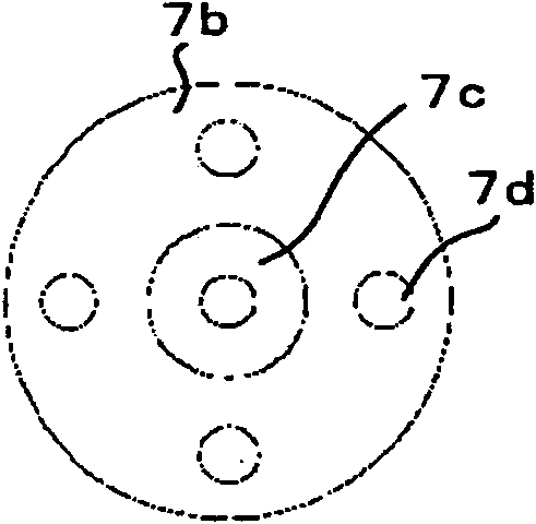
[0018] Conductive members 5, 5 extending...

no. 2 example

[0071] according to Figure 3A , Figure 3B , Figure 3C as well as Figure 3D A second embodiment of the present invention will be described. In the gas insulated switchgear 30 of the second embodiment, two main bus bars are connected to one bus bar for a power supply line via a circuit breaker 31 . That is, the gas insulated switchgear 30 includes a three-phase circuit breaker 31, a bus bar 32 for a power supply line connected to one end of each phase circuit breaker 31, a T-shaped connecting bus bar 33 vertically connected to the other end of the circuit breaker 31, The first main bus circuit breaker 34a arranged at the upper end of the T-shaped connecting bus 33 and the second main bus circuit breaker 34b arranged at the other upper end of the T-shaped connecting bus 33 . The devices constituting the gas insulated switchgear 30 are the same as the above-mentioned first embodiment, constituted by an airtight container and a high-voltage device arranged inside, and its i...


PUM

PropertyMeasurementUnit
Outer diameteraaaaaaaaaa
Thicknessaaaaaaaaaa
Tube chiefaaaaaaaaaa

Abstract

A flexible tube (7) made of a metal bellows made of austenitic stainless steel with a high-flexibility coating applied thereto is employed as gas tubing sections (6a), (6b) connected with sealed containers (1a) to (3b). The flexible tube (7) is provided at both ends with freely rotatable flanges (7b). Using these flanges (7b), the gas tubing is connected with gas ports (8) of the sealed containers. The resistance of the stainless steel flexible tube is high in comparison with copper tubing, and the sheath current can thus be reduced. High-flexibility coating is applied to the outside of the flexible tube. Bending processing of the flexible tube is possible even after coating and weatherability is thereby improved. The support interval of the gas tubing is at least 1 m. Resonance of the gas tubing caused by the frequency of the mains power system thus cannot occur.

Description

technical field [0001] The present invention relates to a gas insulated switchgear, which improves the structure of gas piping in an airtight container. Background technique [0002] A gas insulated switchgear is conventionally known, in which equipment such as a high-voltage conductor and its circuit breaker is arranged in a metal grounded airtight container, and the SF 6 Gas etc. are used to insulate these high-voltage equipment from airtight containers. In this gas-insulated switchgear, gas piping is provided for sucking and exhausting insulating gas into the airtight container. Such gas piping is, for example, disclosed in Japanese Laid-Open Patent Publication, Japanese Patent Laid-Open No. 2004-40963 (hereinafter referred to as Patent Document 1). figure 1 As shown in FIG. 2 , the adjacent airtight containers partitioned by gas are connected, or as shown in FIG. 2 , each airtight container is connected to a gas supply device. In addition, Japanese Laid-Open Patent Pu...

Claims


Application Information

Patent Timeline
IPC IPC(8): H02B13/035H02B13/045
CPCH02B13/045H01H33/56H01H33/561
Inventor 福永雅之冈成信明小卷安昙
Owner KK TOSHIBA
Why Eureka
Try Eureka