Phase frequency detector and charge pump circuit for phase locked loop

A frequency and phase detector and charge pump technology, applied in the field of communication, can solve problems such as poor linearity and noise performance, and achieve the effects of good noise performance, wide output voltage range, and enhanced linearity

Inactive Publication Date: 2011-01-12
WISCOMM MICROSYST SHANGHAI
View PDF0 Cites 9 Cited by
  • Summary
  • Abstract
  • Description
  • Claims
  • Application Information

AI Technical Summary

Problems solved by technology

[0006] In order to solve the problem of poor linearity and noise performance in the prior art, the present invention provides a frequency detector and a charge pump circuit for a phase-locked loop. Set the current so that after the PLL loop is locked, the phase difference between the two input terminals of the PFD deviates from zero, so as to achieve the purpose of enhancing linearity and improving noise performance

Method used


Image

  • Phase frequency detector and charge pump circuit for phase locked loop
  • Phase frequency detector and charge pump circuit for phase locked loop
  • Phase frequency detector and charge pump circuit for phase locked loop

Examples


Embodiment Construction

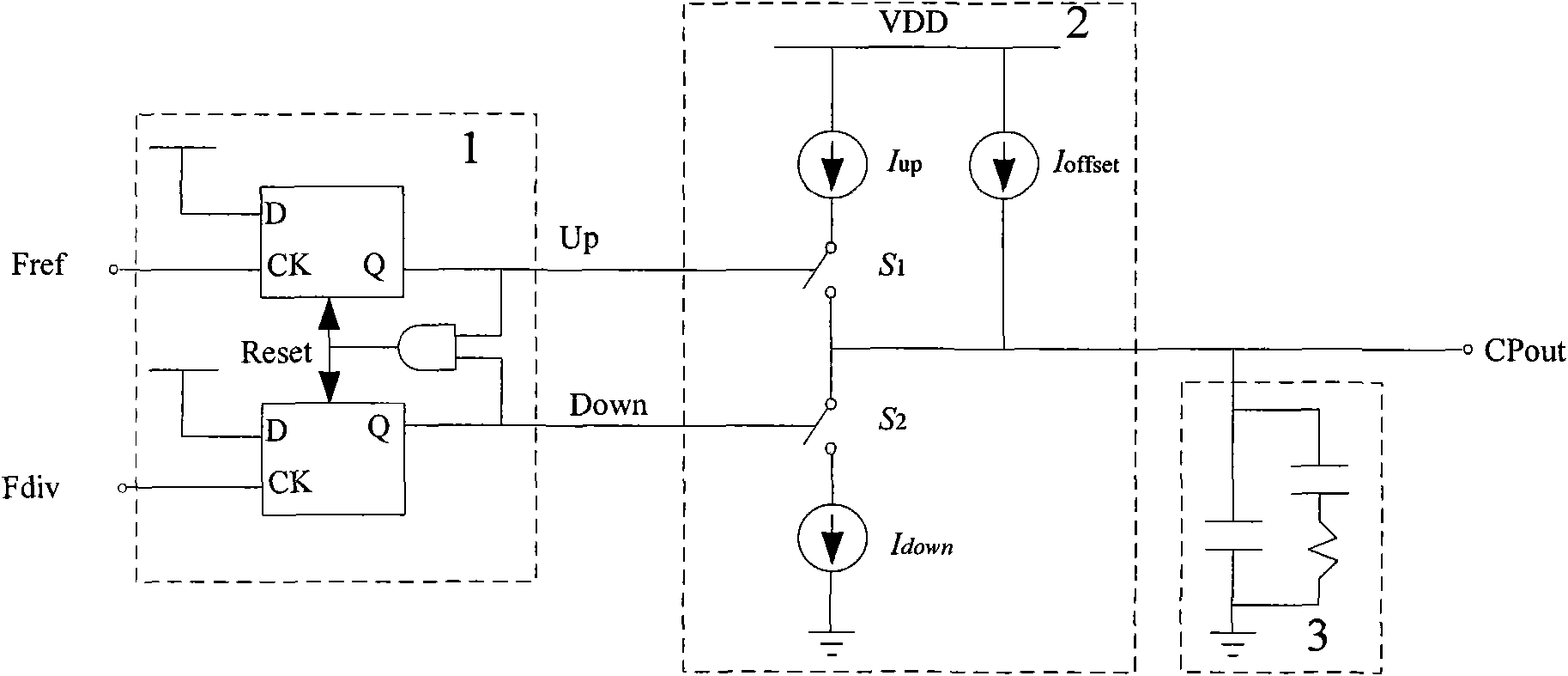
[0027] Such as Figure 4 The frequency detector and the charge pump circuit for the phase-locked loop are shown. The frequency detector 1 outputs the upper Up signal and the lower Down signal to the charge pump 2, and the charge pump 2 is set correspondingly to the two signals. There are a first series circuit and a second series circuit, the first series circuit includes an upper current source Iup and a first controlled switch S1, the second series circuit includes an upper current source Idown and a first controlled switch S2, the first series circuit and The output CPout of the charge pump is drawn between the second series circuits, and the output is connected to the loop filter 3 . The upper current source and the lower current source are respectively connected in parallel with the third series circuit and the fourth series circuit, the third series circuit includes the upper offset circuit Ioff_p and the third controlled switch S3, and the fourth series circuit includes...


PUM


Abstract

The invention provides a phase frequency detector and charge pump circuit for a phase locked loop. The prior art has the defects of poor linearity and noise performance, so when a first series circuit is connected with the output end of a current pump, an upstream biasing circuit is used as a biasing circuit of an upstream current source; and when a second series circuit is connected with the output end of the current pump, a downstream biasing current source is used as a biasing circuit of a downstream current source. By adding the two fixed biasing currents and selecting proper biasing current according to the output voltage of the charge pump, phase difference of two input ends of the phase frequency detector deviates from zero after the PLL loop is locked, so that the aim of enhancing the linearity of the phase frequency detector and the charge pump and improving the noise performance of a fractional-N phase locked loop can be achieved.

Description

technical field [0001] The invention relates to the technical field of communication, in particular to a circuit for improving the linearity and noise performance of a frequency and phase detector and a charge pump in a fractional frequency division phase-locked loop. Background technique [0002] A typical delta-sigma modulator fractional frequency synthesizer such as figure 2 As shown, including delta-sigma modulator and fractional frequency phase-locked loop, fractional frequency phase-locked loop (Frac-N PLL) is mainly composed of phase frequency detector (PFD), charge pump (CP), loop filter (LPF), voltage controlled oscillator (VCO) and frequency divider. Due to the excellent characteristics of fractional frequency PLL, such as high frequency resolution and instantaneous locking speed, it is widely used in radio frequency (RF) circuits. [0003] Traditional phase frequency detector (PFD) 1 and charge pump (CP) 2 such as figure 1 As shown, it can provide a wide frequ...

Claims


Application Information

Patent Timeline
Patent Type & Authority Applications(China)
IPC IPC(8): H03L7/08
Inventor 晏进喜李玺
Owner WISCOMM MICROSYST SHANGHAI
Why Eureka
Try Eureka