Refrigeration equipment

A technology of refrigeration device and shaft current, which is used in the control of electromechanical transmission devices, refrigerators, refrigeration components, etc., can solve problems such as offset, and achieve the effect of improving the accuracy of the same setting and improving the operation efficiency.

Active Publication Date: 2011-01-12
HITACHI JOHNSON CONTROLS AIR CONDITIONING INC
View PDF7 Cites 8 Cited by
  • Summary
  • Abstract
  • Description
  • Claims
  • Application Information

AI Technical Summary

Problems solved by technology

However, the motor constant fluctuates depending on the variation in motor manufacturing and operating conditio

Method used


Image

  • Refrigeration equipment
  • Refrigeration equipment
  • Refrigeration equipment

Examples


Example Embodiment

[0025] Hereinafter, an embodiment of the present invention will be described with reference to the drawings.

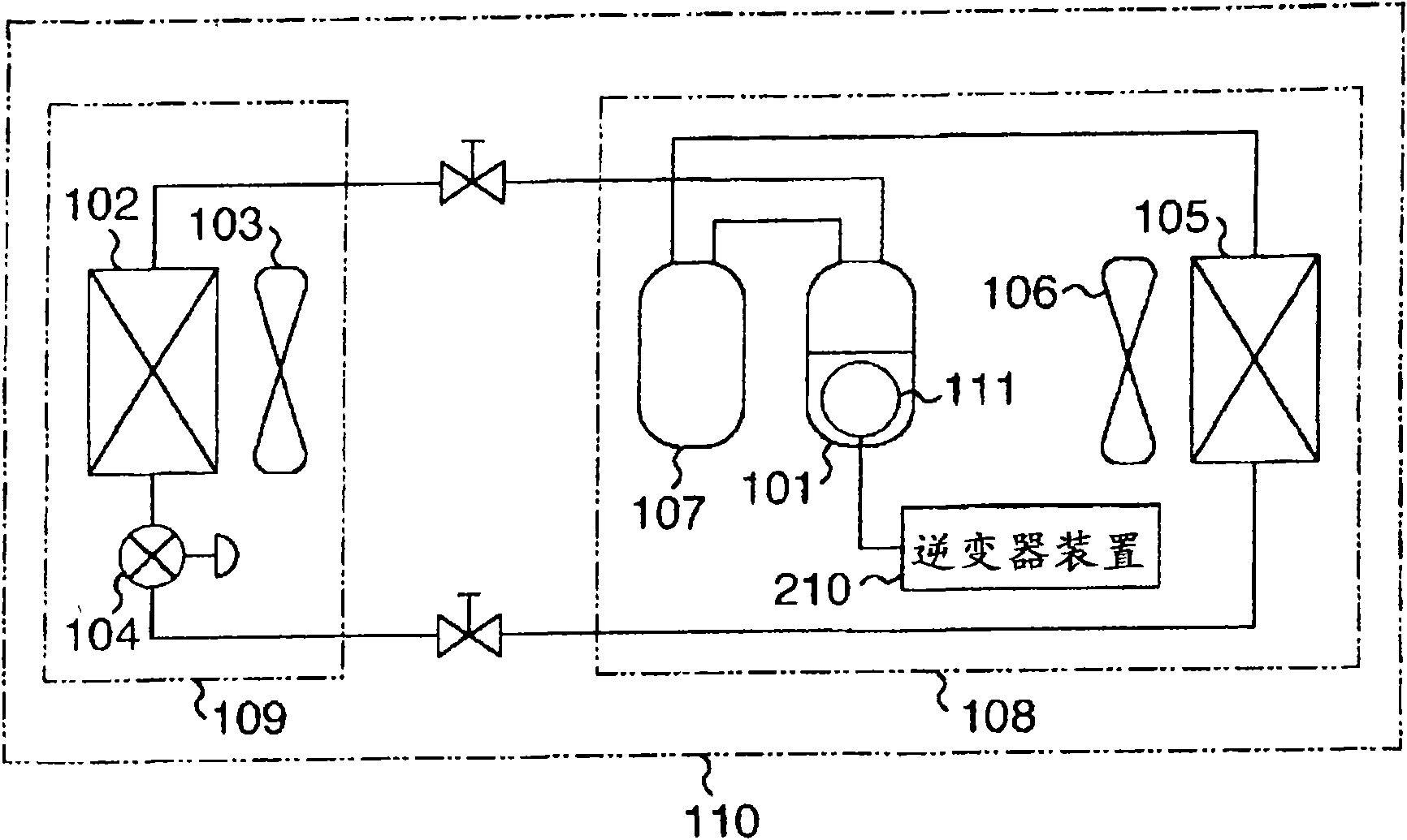
[0026] figure 1 It is a schematic diagram showing the structure of an air conditioner as an embodiment of the present invention.

[0027] At that figure 1 Here, the air conditioner 110 has a refrigeration cycle in which a compressor 101, an indoor heat exchanger 102, an indoor expansion valve 104, an outdoor heat exchanger 105, and an electric storage device 107 are connected in this order. Then, for example, in the case of cooling the room, the refrigerant compressed by the compressor 101 is condensed and liquefied by the outdoor heat exchanger 105, and then decompressed by the indoor expansion valve 104 and evaporated by the indoor heat exchanger 102. And return to compressor 101. In addition, the indoor heat exchanger 102 and the indoor expansion valve 104 are provided in the indoor unit 109, and the indoor unit 109 is provided with an indoor blower 103 for promoting h...


PUM


Abstract

An air conditioner comprises a permanent magnet synchronous motor for driving a compressor in a refrigeration cycle, and an inverter performing variable control of the number of revolutions of the motor by vector control, wherein a microcomputer of the inverter fixes a first d-axis current command value Id* to a predetermined set value while fixing a speed command value omega*, for a predetermined time, as identification mode during vector control operation. An average value is operated by integrating the difference of a second d-axis current command value Id** and the first d-axis current command value Id* in case of the identification mode, a correction amount deltaL* of an inductance set value L* is operated based on the average value, and then vector control operation is performed using an inductance set value L* to which the correction amount deltaL* is added.

Description

technical field [0001] The present invention relates to, for example, refrigerating devices such as air conditioners and refrigerators, and more particularly, to a refrigerating device in which the rotational speed of a permanent magnet synchronous motor driving a compressor of a refrigerating cycle is variably controlled by an inverter device. Background technique [0002] In refrigerating devices such as air conditioners and refrigerators, for example, vector control is employed in inverter devices in order to achieve efficient operation. In vector control, motor constants (specifically, resistance, induced voltage, and inductance) are used, so the motor constants need to be set in advance. However, the motor constant fluctuates depending on variations in motor manufacturing and operating conditions, and there is a possibility that a deviation may occur between a preset value and an actual value. Therefore, a vector control device has been proposed that automatically corr...

Claims


Application Information

Patent Timeline
IPC IPC(8): F25B1/00F24F11/02F24F11/46F24F11/64F24F11/86H02P21/00H02P21/14H02P21/22H02P23/14H02P23/16H02P27/04H02P27/08
CPCF24F11/008Y02B30/741F25B49/025F25B2600/021F24F11/83Y02B30/70F24F11/84
Inventor 栗田佳明安藤达夫高冢邦明大石孝笠原励木下健三浦健太郎
Owner HITACHI JOHNSON CONTROLS AIR CONDITIONING INC
Why Eureka
Try Eureka