Wind-electricity shaft forging die

A wind power and forging die technology, applied in forging/pressing/hammer devices, forging/pressing/hammering machinery, manufacturing tools, etc., can solve the problems of low work efficiency, normal forging of shaft ends, high labor intensity, etc. Work efficiency, ensure the quality of forgings, and reduce the effect of labor intensity

Inactive Publication Date: 2011-01-19
ZHANGJIAGANG CITY GUANGDA MACHINERY FORGING
View PDF8 Cites 4 Cited by
  • Summary
  • Abstract
  • Description
  • Claims
  • Application Information

AI Technical Summary

Problems solved by technology

[0003] 1. Since the wind turbine shaft forging is a large forging, weighing 13.5 tons, the forging die used to forge the forging is heavier, about 30 tons, making it very difficult to turn over the mold with the blank during the forging process. Heavy and troublesome things, high labor intensity and low work efficiency;
[0004] 2. After the shaft end of the billet is inserted into the mold, in the process of thickening the flange head, the contact between the shaft end of the billet and the inner wall of the mold will cool down rapidly, so that the forging temperature cannot be reached after demoulding, so that the billet cannot be corrected after demoulding. For normal forging of the shaft end, the shaft end must be reheated to reach the forging temperature before the shaft end can be forged; however, after the second heating, a coarse grain phenomenon will occur, resulting in a decline in the quality of the forging, which has a great impact on the mechanical properties of the wind turbine shaft. Unable to meet performance requirements at design time

Method used


Image

  • Wind-electricity shaft forging die
  • Wind-electricity shaft forging die

Examples


Embodiment Construction

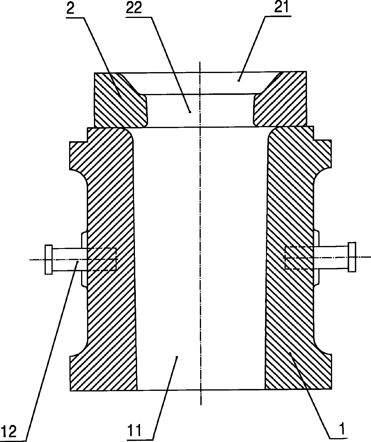
[0011] Specific embodiments of the present invention will be described in detail below in conjunction with the accompanying drawings.

[0012] Such as figure 1 As shown, the wind power shaft forging die described in the present invention has a split structure, including: a die base 1 and a die ring 2 stacked on the die base 1, and the inner hole 11 of the die base 1 is larger than the wind power shaft material The shaft end of the billet is 10-15% larger, and the middle part of the outer wall of the mold base 1 is evenly provided with four hanging bars 12 in the circumferential direction. Cavity 21, the bottom of the cavity 21 is provided with a transition hole 22 through the die ring 2, the transition hole 22 is a tapered hole with a wide upper edge and a narrower lower edge. The height of the transition hole 22 is higher than that of the cavity 21. The height is higher than 45%, and the height of the transition hole 22 is generally set to be 1.5 times the height of the mold...


PUM


Abstract

The invention discloses a wind-electricity shaft forging die which can lighten the labor intensity and improve the working efficiency without secondary heating. The wind-electricity shaft forging die comprises a die holder and a die ring overlapped on the die holder, wherein the inner hole of the die holder is above 10 percent larger than the shaft end of a wind-electricity shaft blank, a cavity corresponding to the neck of the wind-electricity shaft blank is arranged at the top end of the die ring, a transition hole penetrating through the die ring is arranged at the bottom of the cavity, and the transition hole is above 45 percent higher than the cavity. Because the inner hole of the die holder is larger than the shaft end of the blank, the shaft end of the blank is not in contact with the die holder, and secondary heating is not needed, the forging quality of a wind-electricity shaft is ensured and the energy resources are saved. The die holder is detachably connected with the die ring, which greatly facilitates the operation, reduces the labor intensity and improves the working efficiency. Because the transition hole is provided, the accumulation can not happen at the edge of the bottom of the die ring when a flange head is forged, thereby greatly facilitating the normal operation of demoulding.

Description

technical field [0001] The invention relates to a forging die for processing wind power shafts for wind power generation. Background technique [0002] At present, the flange head and the shaft of the shaft end of the wind turbine are forged as an integral structure. Reach 1:2.5. In the traditional forging method, the steps are as follows: first, the billet is released, then the flange head is thickened by putting it into the mold, then the mold is turned over, the mold is placed on the pad, and the forging is separated from the mold by putting the mold release pad from the shaft end. , and then take out the blank, the manipulator clamps the shaft end and throws the flange head round, and after turning around, the manipulator clamps the rounded flange head and then forges the shaft end to make it reach the required size for forging. The main disadvantages of using this traditional forging die for forging are: [0003] 1. Since the wind turbine shaft forging is a large for...

Claims


Application Information

Patent Timeline
IPC IPC(8): B21J13/02
Inventor 丁其华
Owner ZHANGJIAGANG CITY GUANGDA MACHINERY FORGING
Why Eureka
Try Eureka