Self-adaptive centering control system and method for clamp rods of large manipulator
A centering control system and technology of the control system, applied in the field of adaptive centering control system of the tong bar of a large manipulator, can solve the problem of low self-adaptability and automation of forging control, low accuracy and stability, and shortened equipment use Life expectancy and other issues, to achieve the effect of high degree of intelligence and self-adaptation, improve the level of intelligence, and excellent workmanship
- Summary
- Abstract
- Description
- Claims
- Application Information
AI Technical Summary
Problems solved by technology
Method used
Image
Examples
Embodiment 1
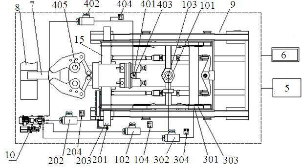
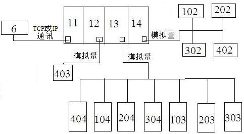
[0037]This embodiment provides an adaptive centering control system for the clamp bar of a large-scale manipulator, which includes a large-scale manipulator, and also includes a PLC control system 5, an HMI human-machine interface 6, a clamp bar tilting unit 3, a clamp bar lifting unit 1 and a clamp The lever translation unit 2, the HMI man-machine interface 6 is connected to the PLC control system 5 through communication, the clamp lever tilting unit 3, the clamp lever lifting unit 1 and the clamp lever translation unit 2 are all electrically connected to the PLC control system 5; The HMI human-machine interface 6 stores the forging models and the centering position data of each pass of the clamp bar corresponding to each forging model.
[0038] The applicable forgings of the present invention include round shaft workpieces and special-shaped workpieces. The tilting unit 3 of the clamp rod is used to control the up and down tilting of the clamp rod. For special-shaped parts, ...
Embodiment 2
[0041] On the basis of Embodiment 1, this embodiment provides an adaptive centering control system for the tong bar of a large-scale manipulator. The large-scale manipulator includes a hanging device, a car body 9 and a tong bar. The hanging device is hinged Installed on the beam in front of the car body 9, the front of the clamp rod is hingedly mounted on the suspension device, the front end of the clamp rod is a jaw 405, and the jaw 405 clamps a forging;
[0042] The clamp lever lifting unit 1 is arranged below the middle part of the vehicle body 9 and is connected with the vehicle body 9, the clamp lever translation unit 2 is connected with the beam 15 of the vehicle body 9, and the clamp lever tilting units 3 are two, respectively symmetrical It is arranged on both sides below the tail portion of the vehicle body 9 and connected with the vehicle body 9 .
[0043] Such as figure 1 As shown, the tong bar is hinged on the car body 9 by a suspension device. The forging workp...
Embodiment 3
[0045] On the basis of Embodiment 2, this embodiment provides an adaptive centering control system for the tong rod of a large-scale manipulator. The rod tilt displacement sensor 303, the clamp rod tilt cylinder 301 communicates with the hydraulic pump station 10 through the pipeline, the clamp rod tilt pressure sensor 304 is connected in series on the pipeline, the clamp rod tilt displacement sensor 303 is fixedly installed on the clamp rod tilt On the outside of the oil cylinder 301, the clamp bar tilt displacement sensor 303 is a stay rope displacement sensor, and its stay rope is connected to the movable plunger of the clamp bar tilt oil cylinder 301. bottom connection;
[0046] The pincer bar tilt cylinder 301 , pincer bar tilt proportional directional valve 302 , pincer bar tilt pressure sensor 304 and pincer bar tilt displacement sensor 303 are all connected to the PLC control system 5 with electrical signals.
[0047] Such as figure 1 As shown, the tilting cylinder 3...
PUM
 Abstract
Description
Claims
Application Information
 - R&D
- Intellectual Property
- Life Sciences
- Materials
- Tech Scout
- Unparalleled Data Quality
- Higher Quality Content
- 60% Fewer Hallucinations
Browse by: Latest US Patents, China's latest patents, Technical Efficacy Thesaurus, Application Domain, Technology Topic, Popular Technical Reports.
© 2025 PatSnap. All rights reserved.Legal|Privacy policy|Modern Slavery Act Transparency Statement|Sitemap|About US| Contact US: help@patsnap.com


