Magnetic field measuring device based on visual guiding robot

A visual guidance and magnetic field measurement technology, applied in the direction of measuring devices, measuring magnetic variables, instruments, etc., can solve problems such as poor safety, failure to meet positioning requirements, and lack of accuracy, so as to improve the level of automation and intelligence, and improve detection efficiency and detection accuracy, to overcome the effect of poor positioning accuracy

Inactive Publication Date: 2010-05-05
HEBEI UNIV OF TECH
View PDF0 Cites 45 Cited by
  • Summary
  • Abstract
  • Description
  • Claims
  • Application Information

AI Technical Summary

Problems solved by technology

The measurement process is manual, which cannot meet the positioning requirements of the specific position of the axis of the through-hole to be measured, the data reliability is low, and the manual measurement process does not have an overload protection device, so the safety of the equipment is poor
The positioning of the manual measurement process is completely based on visual inspection, and there is no accuracy at all. The detection position also depends on manual control, which is labor-intensive.
Generally speaking, the current magnetic field measurement equipment focuses on the measurement of the average magnetic field within a certain range, and mainly emphasizes the magnetic field measurement sensing technology and the driving positioning accuracy of the equipment. Stepping or servo motors, grating rulers, marble platforms, etc. are commonly used. Constructing the driving structure of the magnetic field measurement equipment, the equipment cost is relatively high, and the applicability is limited to a certain extent, especially for the magnetic field measurement for special objects, the degree of automation and intelligence of the equipment still needs to be improved

Method used


Image

  • Magnetic field measuring device based on visual guiding robot
  • Magnetic field measuring device based on visual guiding robot
  • Magnetic field measuring device based on visual guiding robot

Examples


Embodiment Construction

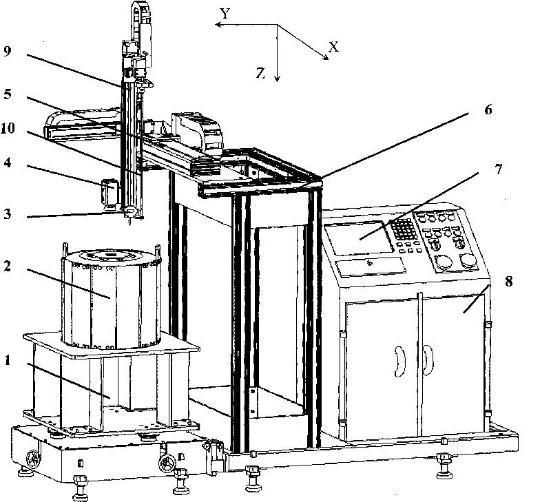
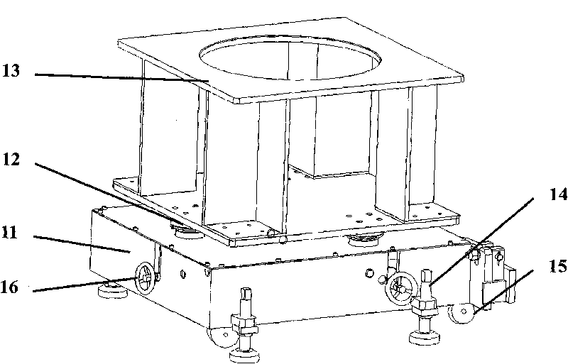
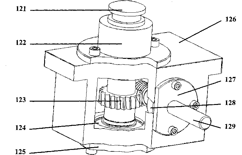
[0022] Below in conjunction with embodiment and accompanying drawing, technical solution of the present invention is described in detail as follows:

[0023] The magnetic field measurement device (hereinafter referred to as the device based on the vision-guided robot designed by the present invention, see Figure 1-6 ) is a device developed according to the special detection requirements of the Institute of Electronics, Chinese Academy of Sciences (for the deep hole detection problems commonly faced by radar multi-beam klystron electromagnetic focusing systems). The technical essential problem to be solved by the device of the present invention is to obtain the precise position of each hole center of the through-hole to be tested in the klystron electromagnetic focusing system through machine vision technology, and realize the magnetic field strength of each through-hole to be tested by dragging the probe with a Cartesian coordinate robot. Measurement. The most important and ...


PUM


Abstract

The invention relates to a magnetic field measuring device based on a visual guiding robot, which is characterized by comprising an adjustable workbench, a measuring system, a robot system and a control system which are matched with each other and have a modular design, wherein the adjustable workbench mainly consists of a base, there sets of adjusting mechanisms, a component placing table, foundation wheels and an adjustable support leg, and the gesture of the adjustable workbench can be adjusted by a hand wheel; the measuring system comprises a gesture measuring device of an object to be detected, a visual guiding positioning device and a magnetic field data collecting device; the gesture measuring device of the object to be detected mainly comprises a number dialgauge and a connecting rod; the visual guiding positioning device mainly comprises an integral camera and an image collecting card which are connected by cables; the magnetic data collecting device mainly comprises a multifunctional data collecting card, a teslameter and a Hall probe which are connected by cables; the robot system comprises a three-dimensional right angle coordinate robot; and the control system comprises an industrial personal computer and software.

Description

technical field [0001] The invention relates to a robot and measurement technology, in particular to a magnetic field measurement device based on a vision-guided or vision-assisted robot. Background technique [0002] Radar is an electronic device that uses electromagnetic waves in the microwave band to detect targets, and it has the characteristics of all-weather and all-weather. Therefore, it has not only become an indispensable electronic equipment in the military, but also widely used in weather forecasting, traffic control, resource detection, environmental monitoring and scientific research and other fields. [0003] With the continuous development and improvement of radar-related technologies, the requirements for the production process and quality of various parts in the processing and manufacturing process continue to increase; and quality inspection is an important means of product quality assurance, and its inspection level will directly affect Quality of product...

Claims


Application Information

Patent Timeline
Patent Type & Authority Applications(China)
IPC IPC(8): G01R33/07
Inventor 李铁军刘今越赵海文杨冬
Owner HEBEI UNIV OF TECH
Why Eureka
Try Eureka