Combined drilling device

A technology for drilling devices and drill pipes, which is applied in the direction of driving devices, drill pipes, and drill pipes for drilling in boreholes, and can solve problems such as frequent accidents in holes, buried drilling, and difficult removal of rock dust and rock particles.

Inactive Publication Date: 2011-01-19
CHENGDU HYDRO ELECTRIC ENG CONSTR OF SINOHYDRO BUREAU 7
View PDF7 Cites 3 Cited by
  • Summary
  • Abstract
  • Description
  • Claims
  • Application Information

AI Technical Summary

Problems solved by technology

[0002] Drilling equipment is required in the drilling construction of the anchorage project. The ordinary drilling tool is directly connected with the drill pipe and the impactor. This construction method will produce a large amount of rock dust and rock particles during the drilling process. Clean up in time, it is easy to cause drill stuck or buried drill accidents in the hole, make the impactor not work normally, and bring many difficulties to the drilling operation
Especially when drilling in complex formations or deep holes, the rock dust and rock particles in the hole are more difficult to get rid of, and the phenomenon of drill stuck and buried drill is particularly prominent, which seriously affects the drilling efficiency and hole quality
[0003] Ordinary drilling tools are directly connected between the drill pipe and the impactor. During the drilling process of ordinary drilling tools, the drilling axis is inclined along the weak layer, and the drilling trajectory is "S" or similar to "parabolic". Accidents in the hole are frequent, and the hole forming accuracy is not high, and the hole deviation cannot be corrected in time
In the drilling construction of anchoring engineering, the design requires that the curvature of the anchor cable hole is ≤2%, so it is difficult to meet the drilling accuracy requirements by conventional drilling methods

Method used


Image

  • Combined drilling device
  • Combined drilling device
  • Combined drilling device

Examples


Embodiment 1

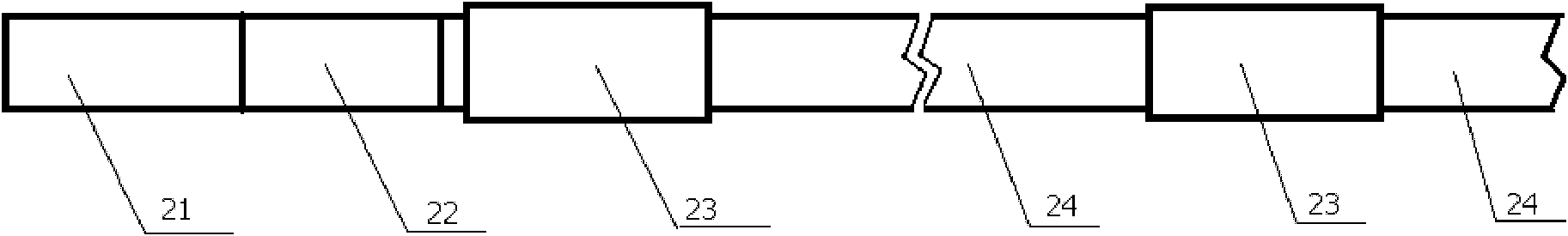
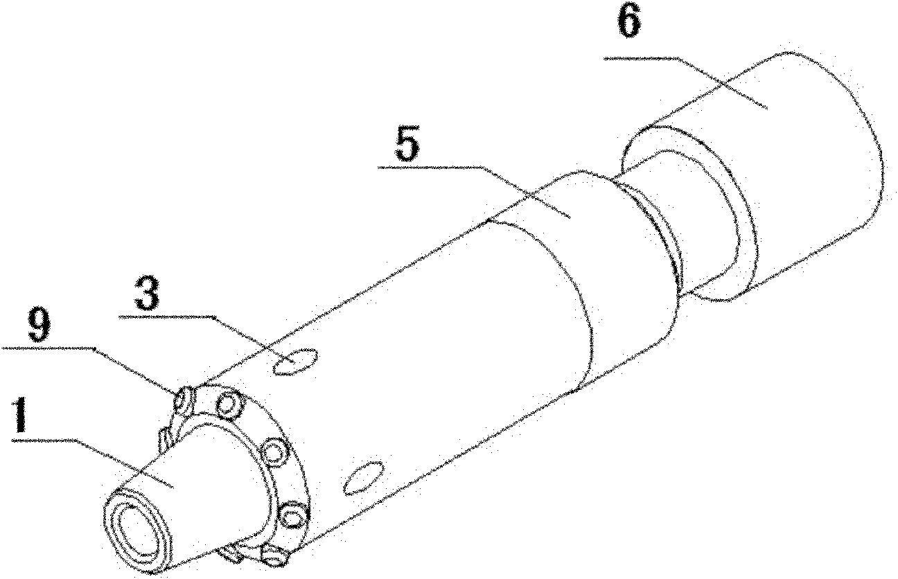
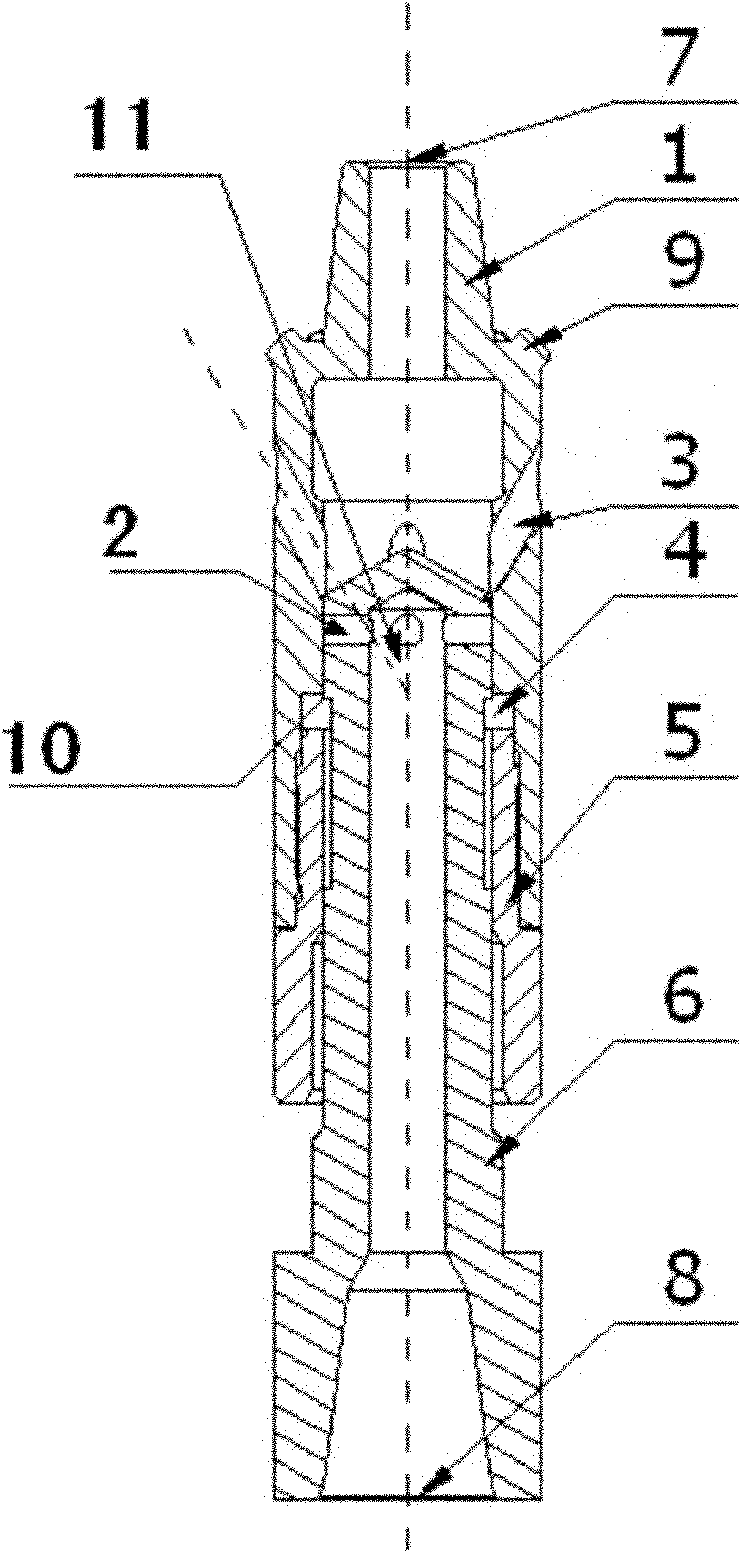
[0038] combine Figure 1 to Figure 7 .

[0039] figure 1 It is a schematic diagram of the connection structure of the device of the present invention, figure 2 It is a schematic diagram of the working state of the reverse blowing grinding device, image 3 It is a schematic diagram of the cross-sectional structure of the working state of the reverse blowing grinding device, Figure 4 It is a schematic diagram of the non-working state of the reverse blowing grinding device, Figure 5 It is a schematic diagram of the cross-sectional structure of the non-working state of the reverse blowing grinding device, Figure 6 It is a schematic diagram of the structure state of the centralizing device without edges and teeth, Figure 7 It is a schematic diagram of the cross-sectional structure of the centralizing device without ribs or teeth.

[0040] figure 1As shown: the down-the-hole impactor 21 is connected with the back blowing grinding device 22, and the back blowing grinding ...

Embodiment 2

[0051] All structures are the same as in Example 1, but the inlaid steel grains 9 can have 3, 6, 12 or 16 pieces, no matter how many inlaid steel grains 9 are there, the purpose is to utilize the grinding and crushing effect of the inlaid steel grains 9 , by grinding and crushing the falling rock blocks in the hole, under the high-pressure wind back blowing, the problems such as drill sticking can be solved, and the drilling efficiency can be improved.

Embodiment 3

[0053] All structures are identical with embodiment 1 or embodiment 2, but vent hole 3 is 6 or 8.


PUM


Abstract

The invention discloses a combined drilling device. The combined drilling device comprises a connectable drill rod and a downhole air hammer, wherein the downhole air hammer is sequentially connected with a back flushing grinding device and a centering device, and then connected with the drill rod; and a drill rod extension part connected after the downhole air hammer is sequentially connected with the back flushing grinding device and the centering device is at least connected with a group of centering devices. The combined drilling device grinds rock flour deposited in a back flushing hole, probe stones which fall on rock masses and are attached to a hole wall and large rock masses, so that the problems of drill clamping and drill burying of a large-diameter drilling tool are solved; and the centering device has the advantages of ensuring that the drilling tool is in the middle of a pore cannel, meeting the requirement on drilling accuracy, enhancing pore-forming quality and solving the problems of drill clamping and drill burying due to large outer diameter under the combination effect of the back flushing grinding device. Due to the combination effect of the device, drilling efficiency is improved and pore-forming quality is enhanced.

Description

technical field [0001] The invention belongs to the field of anchoring engineering drilling machinery manufacturing, in particular to the field of drilling equipment for anchoring engineering drilling machinery, in particular to a combined drilling device. Background technique [0002] Drilling equipment is required in the drilling construction of anchoring engineering. The ordinary drilling tool is directly connected with the drill pipe and the impactor. This construction method will produce a large amount of rock dust and rock particles during the drilling process. Cleaning up in time will easily cause drill stuck or buried drill accidents in the hole, make the impactor not work normally, and bring many difficulties to the drilling operation. Especially when drilling in complex formations or deep holes, the rock dust and rock particles in the hole are more difficult to remove, and the phenomenon of drill stuck and buried drill is particularly prominent, which seriously aff...

Claims


Application Information

Patent Timeline
Patent Type & Authority Applications(China)
IPC IPC(8): E21B4/06E21B17/10
Inventor 李正兵罗建林吕文强鲜少毅
Owner CHENGDU HYDRO ELECTRIC ENG CONSTR OF SINOHYDRO BUREAU 7
Why Eureka
Try Eureka