Right-angle solenoid valve for fire control

A solenoid valve, right-angle technology, applied in the field of electric control valves, can solve the problems of easy scaling, unable to change the direction of water flow, difficult to disassemble and wash, etc., to achieve the effect of ensuring connection reliability, preventing residual sediment, and being easy to disassemble and clean

Inactive Publication Date: 2011-01-19
大连世安科技股份有限公司
View PDF4 Cites 0 Cited by
  • Summary
  • Abstract
  • Description
  • Claims
  • Application Information

AI Technical Summary

Problems solved by technology

The problem is that in this way, an additional water pipe is required between the solenoid valve and the fire extinguishing device to connect the two, which increases the length of the pipeline through which the fire water flows, thus increasing the damping of the water and correspondingly increasing the pressure of the fire water cannon. The loss of the head will shorten the range of the water cannon and weaken the force of the water discharge, thus affecting the fire fighting effect
Moreover, the straight-through solenoid valve in the prior art can only control the passage and disconnection of the water flow, but cannot change the direction of the water flow, and cannot meet the requirements of the existing fire protection environment in the actual application process.
At the same time, the straight-through solenoid valve in the prior art is not easy to disassemble and wash. Since the water flow is only horizontal, it is easy to accumulate scale, and often there is sediment inside, which further hinders the flow of water, especially when fire-fighting equipment is required in case of danger. , bring more difficulties, cannot timely and effectively extinguish the fire, and bring losses to people's lives and property

Method used


Image

  • Right-angle solenoid valve for fire control
  • Right-angle solenoid valve for fire control
  • Right-angle solenoid valve for fire control

Examples


Embodiment Construction

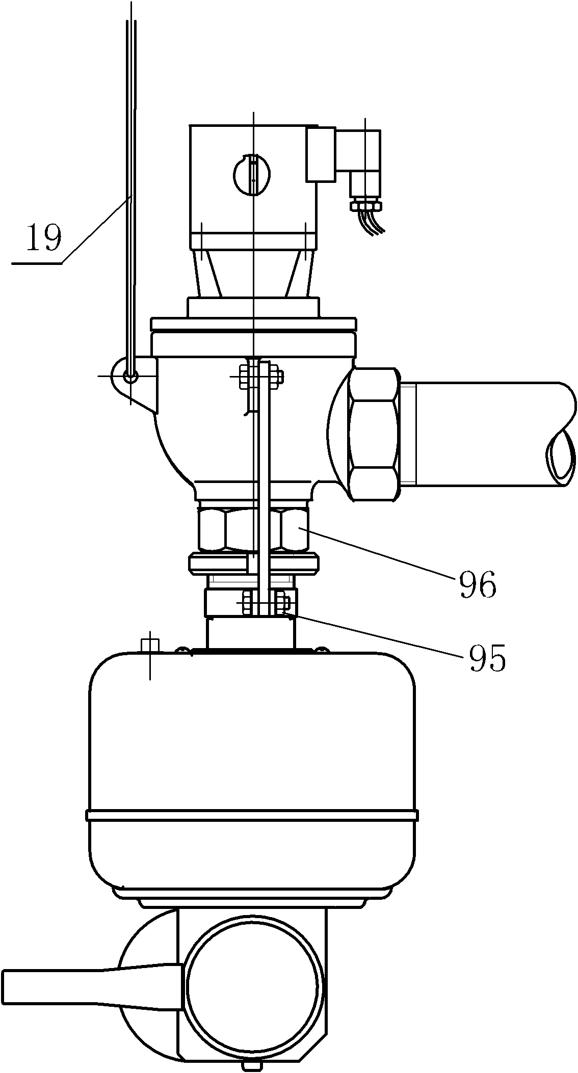
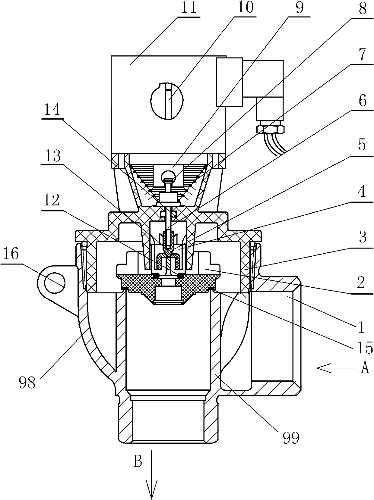
[0018] Such as Figure 1-2 As shown, the right-angle electromagnetic valve of the present invention includes an electromagnetic coil assembly 11, and the electromagnetic coil assembly 11 is at the top of the entire right-angle electromagnetic valve, and a shovel iron guide rod 10 is longitudinally installed in the middle of the electromagnetic coil assembly 11; the electromagnetic coil assembly The bottom of 11 is connected with the upper end of upper cover 3, next to the bottom of electromagnetic coil assembly 11, an inverted truncated cone-shaped return spring 7 is placed inside upper cover 3, and a return spring 7 that can drive return spring 7 is fixed on the inner top of return spring 7. The iron core 9. The lower part of the iron core 9 is provided with a spherical single-mouth groove, and the cylindrical end of the reset valve piston 8 with a small round cake is placed in the groove. On the reset valve piston 8 and expose the bottom end baffle plate of the reset valve ...


PUM


Abstract

The invention discloses a right-angle solenoid valve for fire control, comprising a transverse valve inlet (A), a valve plug through which inlet water flows and a vertical valve outlet (B) below the valve plug, wherein, a ring-shaped tube wall (99) below the valve plug separates the valve inlet (A) from the valve outlet (B). The invention substitutes the right-angle valve body for the traditional straightway valve bodies of the straightway solenoid valves. The right-angle valve body of the invention can change the water flow direction and better meet the fire extinguishment requirement. At the same time, the right-angle solenoid valve changes the arrangement modes of the water flow channels of the common straightway solenoid valves in the prior art and adopts two water flow channels vertically communicated with each other, thus reducing water scale. The device of the invention adopts a detachable upper cover to connect the valve body with other components, thus being easy to detach and clean and effectively preventing precipitates from leaving. A lug arranged outside the valve body can better install and fix the solenoid valve of the invention, thus ensuring the solenoid valve to be safer and more reliable.

Description

technical field [0001] The invention relates to an electric control valve, more specifically, to a solenoid valve for fire protection. Background technique [0002] Now, fire-fighting equipment is installed in various places, and the common fire-fighting equipment in large-scale places is the fire monitor that adopts pipeline water supply, and electromagnetic valve is all installed on the fire monitor. Under the existing technology, such as Figure 5 As shown, the solenoid valve installed on the fire monitor is a straight-through type, and the water flow passes through it in a straight line. The specific installation method is as Image 6 As shown, after the fire-fighting water passes through the straight-through electromagnetic valve 21, it flows through the straight pipe and the bent pipe to the fire-fighting water monitor 21. The problem is that in this way, an additional water pipe is required between the solenoid valve and the fire extinguishing device to connect the ...

Claims


Application Information

Patent Timeline
Patent Type & Authority Applications(China)
IPC IPC(8): F16K31/06F16K27/02
Inventor 宗延杰
Owner 大连世安科技股份有限公司
Why Eureka
Try Eureka