Imaging optical system

A technology of imaging optics and image plane side, which is applied in optics, optical elements, diffraction gratings, etc., can solve the problems of image deterioration, processing and assembly time, and yield decline, etc., and achieve the effect of compact imaging optical system

Active Publication Date: 2012-07-25
NALUX CO LTD
View PDF3 Cites 0 Cited by
  • Summary
  • Abstract
  • Description
  • Claims
  • Application Information

AI Technical Summary

Problems solved by technology

However, in this method, the tolerance of the second lens with a large negative refractive power is relatively strict, and if it exceeds the range of the tolerance, large aberrations will occur as the maximum field of view is approached, resulting in blurred images. deterioration
[0004] In order to manufacture such an optical system with strict tolerances, it takes time for processing and assembly, and when only the optical system that passes the inspection after production is regarded as a good product, the yield rate decreases.
In either case, the result is an increase in the manufacturing cost of the imaging optics
[0005] On the other hand, through the development of backside illumination (BSI) of CMOS (Complementally Metal Oxide Semiconductor: Complementary Metal Oxide Semiconductor) imaging sensor, the allowable incident angle of light to the sensor is expanded, but the advantages of this technology are used as manufacturing time. The design and development work brought out by the advantages of the system is still in a state of no progress

Method used


Image

  • Imaging optical system
  • Imaging optical system
  • Imaging optical system

Examples


Embodiment 1

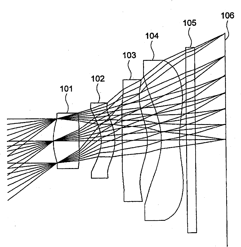
[0083] figure 1 It is a figure which shows the structure of the imaging optical system of Example 1. The imaging optical system of Example 1 includes a first lens 101 , a second lens 102 , a third lens 103 , and a fourth lens 104 from the object side to the image side. The diaphragm is closer to the object side than the image-side surface of the first lens 101 , and is closer to the image side than the apex of the object-side surface of the first lens 101 . Specifically, the aperture is located on the object-side surface of the first lens 101 . The light passing through the first lens 101 , the second lens 102 , the third lens 103 , and the fourth lens 104 passes through the glass plate 105 and reaches the image plane 106 .

[0084] In this embodiment, a diffraction grating for decolorization is provided on the image plane side of the first lens. In this embodiment, the achromatic function is mainly performed by a diffraction grating, and the number of zones of the diffract...

Embodiment 2

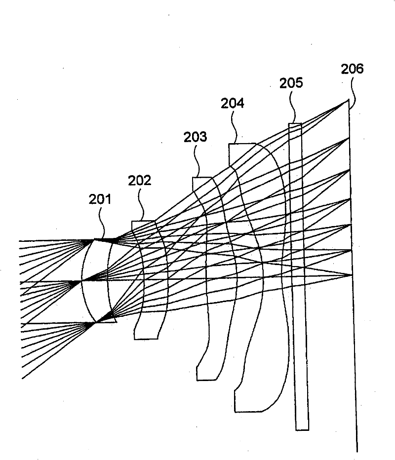
[0102] image 3 It is a figure which shows the structure of the imaging optical system of Example 2. The imaging optical system of Example 2 includes a first lens 201 , a second lens 202 , a third lens 203 , and a fourth lens 204 from the object side to the image side. The diaphragm is closer to the object side than the image-side surface of the first lens 201 , and is closer to the image side than the apex of the object-side surface of the first lens 201 . Specifically, the aperture is located on the object-side surface of the first lens 201 . The light passing through the first lens 201 , the second lens 202 , the third lens 203 , and the fourth lens 204 passes through the glass plate 205 and reaches the image plane 206 .

[0103] In this embodiment, a diffraction grating for decolorization is provided on the image plane side of the first lens. In this embodiment, the achromatic function is mainly undertaken by the diffraction grating, and the number of zones of the diffr...

Embodiment 3

[0121] Figure 5 It is a figure which shows the structure of the imaging optical system of Example 3. The imaging optical system of Example 3 includes a first lens 301 , a second lens 302 , a third lens 303 , and a fourth lens 304 from the object side to the image side. The diaphragm is closer to the object side than the image-side surface of the first lens 301 , and is closer to the image side than the apex of the object-side surface of the first lens 301 . Specifically, the aperture is located on the object-side surface of the first lens 301 . The light passing through the first lens 301 , the second lens 302 , the third lens 303 , and the fourth lens 304 passes through the glass plate 305 and reaches the image plane 306 .

[0122] In this embodiment, a diffraction grating for decolorization is provided on the image plane side of the first lens. In this embodiment, the achromatic function is mainly performed by a diffraction grating, and the number of zones of the diffrac...


PUM


Abstract

Provided is an imaging optical system which comprises, sequentially from the object side to the image surface side, a first lens having a positive power, a second lens which is a meniscus lens having a convex surface on the image side, a third lens having a positive power, and a fourth lens having a negative power. The power of the third lens in the vicinity of the principal ray in the meridional direction is positive in the paraxial area, and is negative in an area distant from the optical axis. The power of the fourth lens in the vicinity of the principal ray in the meridional direction is negative in the paraxial area, and is positive in an area distant from the optical axis. The first lens is provided with diffraction gratings on the image side surface. If it is assumed that the focallength of the second lens is f2, the resultant focal length of the imaging optical system is fT, and the distance between the aperture stop or the apex of the object side surface of the first lens, whichever is closer to the object side, and the image surface is TTL, the following formulae are satisfied; |f 2 / f T | >= 3 (1) TTL / f T <= 1.2 (2).

Description

technical field [0001] The present invention relates to imaging optical systems used in digital cameras, mobile phones with imaging functions, scanners and the like. Background technique [0002] There is an increasing demand for small, high-resolution imaging devices. Therefore, miniaturization and high resolution are also required for imaging optical systems used in such imaging devices. Such imaging optical systems are described, for example, in Patent Documents 1 to 3 and the like. [0003] Recently, as a means of downsizing the imaging optical system, there is a tendency to adopt a method of widening the angle of view more often. In a solid-state imaging device, in order to minimize the blocking of light by the wall of the wiring layer, it is necessary to limit the incident angle of light to the imaging device, and to correspond to widening the angle, it is necessary to forcibly control the angle of light within a predetermined angle range. . Generally, in a compact...

Claims


Application Information

Patent Timeline
Patent Type & Authority Patents(China)
IPC IPC(8): G02B13/10G02B13/00G02B5/18
CPCG02B5/189G02B13/18
Inventor 金井纪文约耳・科维尔
Owner NALUX CO LTD
Why Eureka
Try Eureka