Light-emitting diode (LED) illuminating light path for projector

A technology of LED lighting and LED light source, which is applied in optics, instruments, optical components, etc., can solve the problems of poor optical system matching, poor color uniformity of light spots, inconsistent light spots of monochromatic light sources, etc., and achieves improved color uniformity and uniform color good sex effect

Inactive Publication Date: 2011-01-19
GUANGDONG VTRON TECH CO LTD
View PDF5 Cites 13 Cited by
  • Summary
  • Abstract
  • Description
  • Claims
  • Application Information

AI Technical Summary

Problems solved by technology

However, in this scheme, since the optical path lengths of the two color light sources are the same, while the optical path length of the other color light source is relatively short, and finally the three color lights are concentrated by the same lens group, so the matching degree of the optical system is poor, and the single The light spots of the color light sources are inconsistent, resulting in poor color uniformity of the final lighting spots after light combination

Method used


Image

  • Light-emitting diode (LED) illuminating light path for projector
  • Light-emitting diode (LED) illuminating light path for projector
  • Light-emitting diode (LED) illuminating light path for projector

Examples


Embodiment approach 2

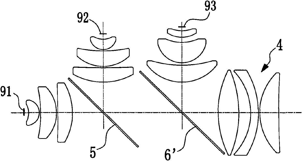
[0027] The difference between this embodiment and Embodiment 1 is: figure 2 As shown, the fourth lens group 4 is arranged on the main optical axis, and the second dichroic mirror 6' is a blue-green anti-red dichroic mirror. In this embodiment, the green light is transmitted only once, so higher projection brightness can be obtained.

Embodiment approach 3

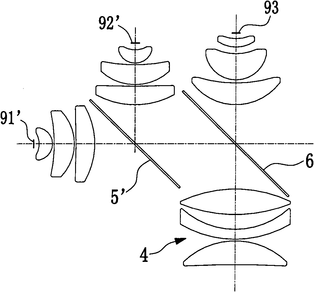
[0029] The difference between this embodiment and Embodiment 1 is: image 3 As shown, the first, second, and third LED light sources 91', 92', and 93 are green, blue, and red LED light sources respectively, and the first dichroic mirror 5' is a green-transmissive and blue-transmissive dichroic mirror. In this embodiment, the green light is only transmitted once, so higher projection brightness can also be obtained.

[0030] The present invention can also exchange the positions of blue light, green light and red light, and change the corresponding dichroic mirror and the placement position of the fourth lens group at the same time, so as to achieve the same similar effect. For example, the blue and red LED light sources use the first and second lens groups with the same optical path length and structure, while the green LED light source uses the third lens group with a shorter optical path length. And adjust the dichroic mirror and the fourth lens group accordingly. Finally, ...


PUM


Abstract

The invention relates to a light-emitting diode (LED) illuminating light path for a projector. The illuminating light path comprises a first LED light source, a second LED light source, a third LED light source, a first lens group, a second lens group, a third lens group, a first dichroic mirror, a second dichroic mirror and a fourth lens group, wherein the first, second and third lens groups are used for converging the first, second and third LED light sources into near parallel light; the first dichroic mirror is used for combining the near parallel light of the first and second lens groups; the second dichroic mirror is used for combining the combined light obtained by the first dichroic mirror with the parallel light of the third lens group; the fourth lens group is used for converging the combined light obtained by the second dichroic mirror into light spots; moreover, the light paths of the first lens group and the second lens group have the same length and adopt the same lens group; the light path of the third lens group is shorter than that of the first or second lens group; and the light spots obtained by converging the parallel light emitted from the first, second and third lens groups through the fourth lens group have high consistency. The light spots obtained by light combination have high color uniformity, so that the color uniformity of the projector is improved to a certain extent.

Description

technical field [0001] The invention relates to an LED lighting light path for a projector. Background technique [0002] With the improvement of actual demand, higher requirements are put forward for projectors, focusing on brightness improvement, environmental protection, price reduction, etc., and the emergence of LEDs better adapts to this trend. Because LED has the characteristics of sensitive response, high luminous efficiency, longer service life, higher color saturation, and no toxic substances, it is widely used in backlight, display, lighting and other fields. At present, projectors have also begun to use LEDs as lighting sources, but compared with traditional bulbs, there is still a gap in brightness to some extent, and the light distribution angle of LEDs is relatively large, which affects the performance of projectors. Therefore, developing an LED lighting light path suitable for projectors has become an urgent problem to be solved. [0003] In order to obtain...

Claims


Application Information

Patent Timeline
IPC IPC(8): G02B27/18G02B27/10G03B21/20
Inventor 王鑫
Owner GUANGDONG VTRON TECH CO LTD
Why Eureka
Try Eureka